 |
|||
|
|
|||
|
|
|||
| ||||||||||
|
|
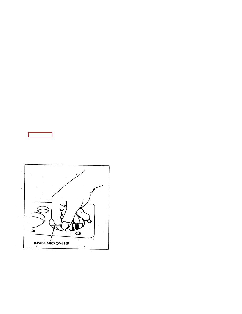
 indicator up and down in cylinder and note largest and
(2) Tappet travels 0.002 to 0.006 inch,
smallest indications. The difference between indications
through rotator clearance, lifting keys from valve stem
is the amount of taper of the cylinder. If out of round or
contact, but not yet lifting valve. Valve can turn now, as
taper exceeds 0.004 inch or if overall wear exceeds
keys no longer grip it at stem.
0.008 inch, rebore cylinder walls and install oversize
(3) Continued lift of tappet raises valve
pistons and rings.
through push on cap. Valve will rotate slightly each time
(11) Compare' cylinder bore measurements
it opens, due to various forces acting on it.
with diameter when new and determine whether to
b. Removal.
rebore to 0.020 or 0.040 inch oversize.
(1) Remove cylinder head, manifold, and
(12) Rebore all cylinders with cylinder boring
valve covers.
equipment to same predetermined oversize.
Plug oil return holes in block with rags, to prevent
dropping parts into oil pan.
(2) With
conventional
valve
spring
NOTE
compressor, raise spring retainer and valve spring
enough to remove cap and two keys. With these parts
Engine will now need pistons and
removed, lift valve from engine block, and place in
rings in oversize corresponding to
numbered valve rack so each valve can be identified,
new cylinder bore diameter.
and returned to the same port from which it came. Keep
components from each valve together to reduce the
(13) When cylinder bores have been finished to
amount of adjusting at reinstallation.
size, coat walls with OE to: prevent rusting.
c. Inspection.
(1) Inspect valve for burning at the neck,
6-83.
VALVES.
below head of valve, carbon formation on head or stem,
or pitting of stem or face of valve.
a. Description. The engine valves are equipped
(2) Inspect valve seat in block for burning or
with valve rotators, which consist of a special seat
uneven seating of valve. Inspect valve guide for wear or
retainer (Figure 6-40), a cap, a pair of flat half-round keys,
gumming from carbon deposits.
and a special shaped valve stem. The lift cycle of the
d. Repair.
valve is as follows:
(1) Original valves in this engine are not to be
(1) Tappet travels through normal valve
serviced for any reason. If they are found to be
clearance to contact cap.
unserviceable, replace. with new valves.
(2) Service replacement:
valves with
conventional valve grinding techniques.
Grind
replacement valve faces to 45 deg. angle, with 1/16 inch
margin, on standard shop valve grinder, and reface valve
seats to same angle.
(3) Replace exhaust valve seat inserts which
are beyond practical repair, using standard procedure of
pulling old insert and driving in a new insert which has
been chilled in dry ice for twenty minutes.
(4) Replace valve guides worn beyond 0.0025
clearance as follows: (a) Run tappet adjusting screws all
the way down and turn engine so tappet is off cam lobe.
(b) Drive out guides with 1/2 inch diameter
drift, with 5/16 inch diameter pilot. Drive in new guides
with same pilot to same depth as old guides.
Figure 6-39. Measuring Cylinder Bore
111
|
|
Privacy Statement - Press Release - Copyright Information. - Contact Us |