 |
|||
|
|
|||
|
Page Title:
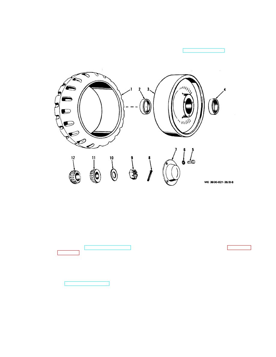
Figure 8-6. Steering wheel assembly exploded view. |
|
||
| ||||||||||
|
|
 TM 10-3930-621-34
b. Steering Wheel Assembly. Refer to fig and
disassemble as follows:
(2) Remove hub cap (7), cotter pin (8), wheel nut
(1) If inspection indicates replacement is
(9), washer (10), inner bearing cone (12), ax outer
necessary, remove tire (1) from wheel (3) (para 8 17).
bearing cone (11) (TM 10-3930-621-12
(3) Using bearing cup puller, remove bearing
cups (2 and 4) from wheel (3).
1.
Tire
7. Hub cap
2.
Inner bearing cup
8. Cotter pin
3.
Wheel
9. Nut
4.
Outer bearing cup
10. Flat washer
5.
Bolt
11. Outer bearing cone
6.
Lock washer
12. Inner bearing cone
Figure 8-6. Steering wheel assembly exploded view.
8-14. Cleaning, Inspection, and Replacement
8-15. Assembly
a.
Inspect tire for wear
(TM10-3930-621-12)
a. Drive Wheel Assembly. Refer to figure 8-5 and
replace if necessary (para 8-17).
assemble as follows:
b. Clean all parts with cleaning compound solvent
(1) Press bearing cups (3 and 7) in wheel hub
(Spec. P-S-661). Dry thoroughly with compressed air.
with paper taper to outside of wheel. Tap in place evenly
c. Inspect bearing cones and cups, wheels, bull gear
around edge of cup.
for damage and excessive or uneven wear.
Caution : Pressure must be evenly distributed
d. Replace all parts as authorized.
on cups to avoid damage and cocking.
e. Repack bearings (TM 10-3930-621-12).
(2) Install pins (11 and 12) in bull gear (2).
8-8
|
|
Privacy Statement - Press Release - Copyright Information. - Contact Us |