 |
|||
|
|
|||
|
Page Title:
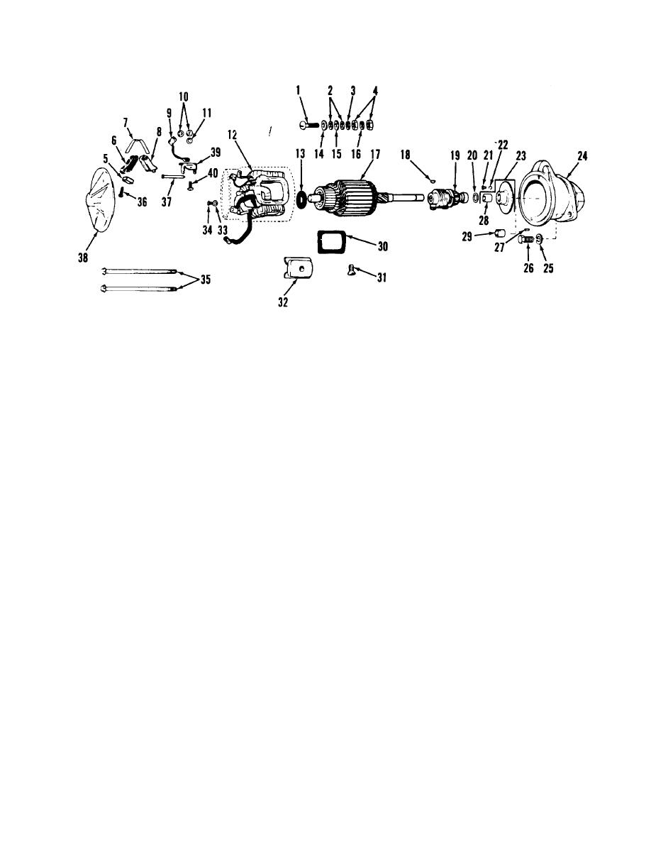
Figure 5-5. Starter, exploded view |
|
||
| ||||||||||
|
|
 TM 10-3930-621-34
1. Stud
15.
Lock washer
28.
Center bushing
2. Flat washer
16.
Terminal bushing
29.
Drive bushing
3. Flat washer
17.
Armature
30.
Insulator
4. Nut
18.
Key
31.
Screw
5. Brush
19.
Drive assembly
32.
Pole
6. Brush holder
20.
Thrust washer
33.
Lock washer
7. Brush spring
21.
Screw
34.
Screw
8. Brush holder
22.
Lock washer
35.
Thru-bolt
9. Lead
23.
Center bearing
36.
Screw
10. Nut
24.
Housing
37.
Support
11. Lock washer
25.
Lock washer
38.
Frame
12. Fieldwinding
26.
Cap screw
39.
Support
13. Washer
27.
Pin
40.
Screw
14. Flat washer
Figure 5-5. Starter, exploded view
d.
Carefully inspect armature commutator.
If
5-12. Inspection and Repair
burned, rough or out-of-round, turn down as follows:
a. Clean starter motor parts with cleaning
(1) Place armature in lathe and turn down
compound, solvent (Spec. P-S-661). Do not use
commutator until true. Make certain cut is not made on
cleaning solvents on drive mechanism or armature and
commutator riser bars as solder will be removed, thus
field coils. Dry parts with compressed air.
weakening coil connections at this section. Remain
b.
Check bushings for roughness, scoring or
approximately 3/16" from riser bars. Remove no more
excessive clearance. Bushing running clearances are as
than 0.03 of an inch from the face of the commutator.
follows: commutator end frame 0.0013" - 0.0090", center
(2) Check armature on a growler for shorts. Refer
bushing and drive housing bushing 0.0015" -0.0050"
to 5-13a
c. Check brush holders to be sure they will properly
hold brushes against commutator. Check spring tension
which should be 35 ounces. Check condition of brushes;
if
pitted
or
worn,
replace.
5-6
|
|
Privacy Statement - Press Release - Copyright Information. - Contact Us |
