 |
|||
|
|
|||
|
Page Title:
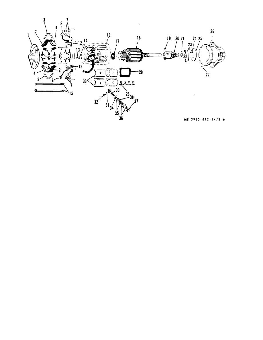
Figure 3-6. Starter motor, disassembly and reassembly/ |
|
||
| ||||||||||
|
|
 1 End frame
20 Drive mechanism
2 Brush holder
21 Washer
3 Spring
22 Screw
4 Brush holder
23 Washer
5 Brush
24 Bushing
6 Screw
25 Bearing assembly
7 Nut
26 End frame (drive housing)
8 Lead
27 Pin
9 Washer
28 Screw
10 Shaft
29 Insulator
11 Screw
30 Pole shoe
12 Holder
31 Washer
13 Screw
32 Screw
14 Washer
33 Stud
15 Through bolts
34 Grommet
16 Field coil
35 Washer
17 Spacer
36 Washer
18 Armature
37 Nut
19 Ken
38 Washer
Figure 3-6. Starter motor, disassembly and reassembly/
(3) Disconnect field lead from brush holders
(8) Drive mechanism (20) is keyed onto
(2 and 4) and remove commutator end frame (1) from
armature shaft and is removed by pressing off or using a
field frame.
puller.
c. Cleaning, Inspection and Repair. Clean, inspect
(4) Brushes (5) brush holders 12 and 4) and
springs (3) can now be removed from commutator end
and repair as directed in TM 5-764.
d. Reassembly.
frame.
(5) Do not remove field coils. If tests indicate
(1) Install field frame terminal stud (33) and
coils are defective, replace starting motor.
then connect heavy field lead to stud (33).
(6) Remove terminal stud from field frame by
(2) Install brush holders (2 and 4), brushes
removing nuts (37), washers (35, 36, and 38) and rubber
(5), and springs (3) on commutator end frame (1).
grommet (34).
Place end frame on field frame and connect
(7) Remove capscrews (22) which mount
undergrounded brush leads to field coil terminals.
center bushing (24) on drive end housing (26) and
(3) Install center bearing (25) on armature
remove housing from armature.
shaft with long side toward commutator end of armature.
(4) Install key (19) in armature shaft (18) and
3-6
|
|
Privacy Statement - Press Release - Copyright Information. - Contact Us |