 |
|||
|
|
|||
|
Page Title:
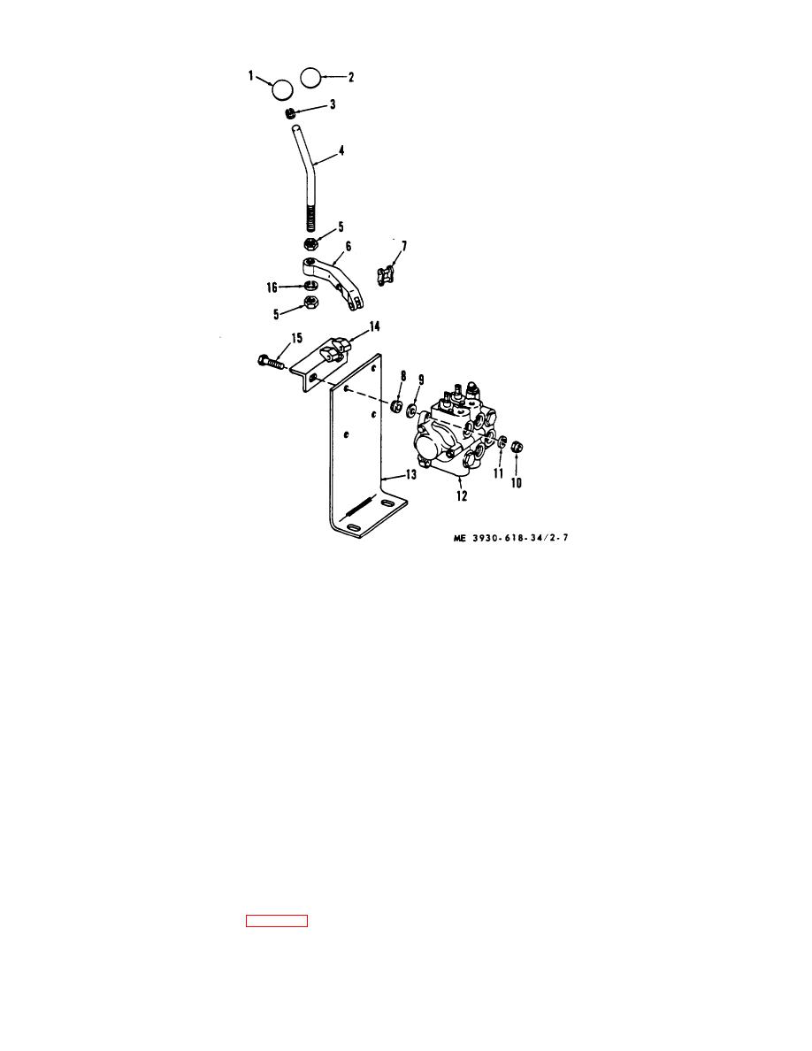
Figure 2-7. Hydraulic control valve removal and installation. |
|
||
| ||||||||||
|
|
 1 Knob
9 Flat washer
2 Knob
10 Nut
3 Bushing
11 Lockwasher
4 Handle
12 Control valve
5 Nut
13 Bracket
6 Lever
14 Bracket
7 Link
15 Screw
8 Bushing
16 Lockwasher
Figure 2-7. Hydraulic control valve removal and installation.
(5) Replace nuts (10) and washers (11) or
(1) Raise rear end of truck with chain hoist to
screws 115) to hold bracket (14) in place.
a workable height and support in this position with blocks
b. Removal (Control levers)
or other authorized safe means.
(2) Place a suitable jack under the steering
(1) Remove links (7) attaching levers (6) to
axle to raise it slightly. This removes weight stress from
bracket (14).
the trunnion supports and supports axle during removal.
(2) Remove lower nuts (5) and lockwashers
(3) Detach steering yoke from ball stud on
(16) from handles (4). Loosen upper nuts (5) and screw
pivot arm.
handles from levers.
(4) Remove from capscrews attaching the
(3) Remove knobs (1 and 2) from handles.
c. Installation. Install hydraulic control valve by
trunnion support assemblies.
(5) Lower axle assembly to ground.
reversing the procedure in a & b above.
2-14. Steering Axle Assembly
a. Removal. Refer to figure 2-8 and proceed
a follows:
2-13
|
|
Privacy Statement - Press Release - Copyright Information. - Contact Us |