 |
|||
|
|
|||
|
Page Title:
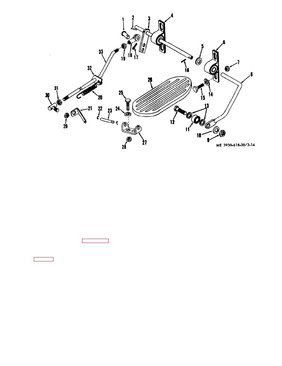
Figure 2-14.Accelerator pedal and linkage. exploded view. |
|
||
| ||||||||||
|
|
 Yoke. adjustable
18.
I. Pin. yoke
Nut
19.
2. Pin, roll
Spring
20.
3. Lever
Angle
21.
4. Block
Ring, retaining
22.
5. Washer, Hat
Pin, hinge
23.
8. Block
Washer, lock
24.
7. Nut
screw
25.
8. Shaft
Pedal
26.
9. Nut
Bracket
27.
10. Washer, lock
Nut
28.
11. Bearing
Nut
29.
12. screw
Rod, end
30.
13. Washer, flat
Nut
31.
14. Washer, luck
Clip
32.
15. screw
Accelerator rod
33.
16. Pin, roll
17. Pin, cotter
Figure 2-14.Accelerator pedal and linkage. exploded view.
(5) From inside the driver compartment, remove
2-21. Fuel-Tank
the screws, washers, and nuts which secure the tank
to the support brackets.
fuel tank as follows :
(6) Lower the tank, being careful not to damage
the shutoff valve.
(1) Close the fuel shutoff valve at the fuel filter
b. Installation. Reverse procedures in a above.
c. Cleaning.
fitting.
(1) Remove the filler assembly from the top of
(2) Attach a length of hose to the shutoff valve
the tank and clean the strainer.
fitting and drain the tank through the hose. Total
(2) Remove the shutoff valve and elbow from
tank capacity is 14.5 gallons. Choose container accord-
the tank. Remove the drain plug and allow any sedi-
ingly.
ment or water to drain out.
(3) Remove the screws and lockwashers, from the
(3) Clean the outside of the tank with PD-680.
outeredge of the mounting plate and lift the cowl away
(4) Clean the inside of the tank with PD-680 and
from the mounting plate.
then drain.
(5) Allow the tank to dry thoroughly before re-
(4) Disconnect wire from the sending unit ter-
filling it with fuel.
minal at the top of the tank.
2-21
|
|
Privacy Statement - Press Release - Copyright Information. - Contact Us |