 |
|||
|
|
|||
|
Page Title:
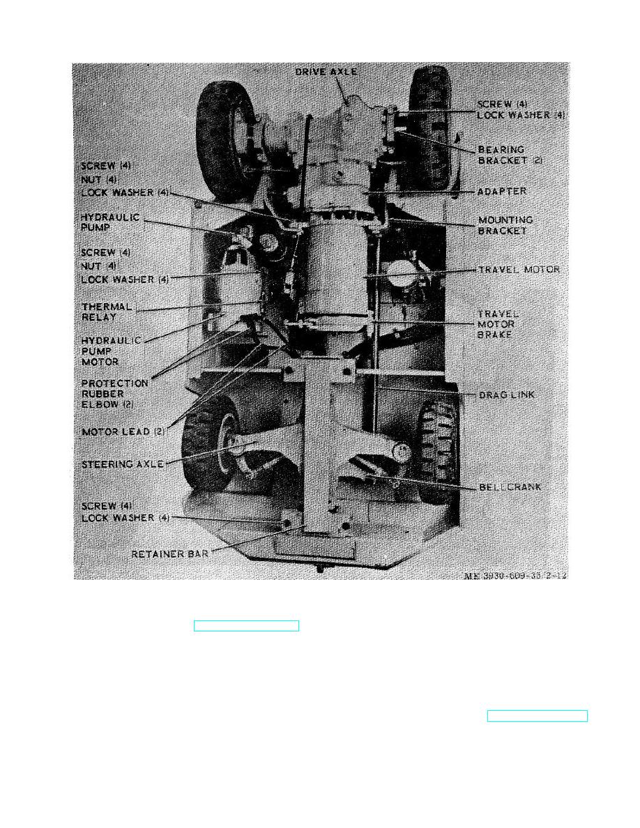
Figure 2-12. Hydraulic pump motor, drive axle and steering axle. |
|
||
| ||||||||||
|
|
 TM 10-3930-609-35
Figure 2-12. Hydraulic pump motor, drive axle and steering axle.
(1) Remove floor plate (TM 10-3930-609-12).
b. Installation.
(2) Disconnect inlet elbow (fig. 210) and
(1) Position hydraulic pump on pump motor,
outlet hose at hydraulic pump and cap ends to prevent
being certain coupling halves engage properly and
entrance of dirt.
secure in place with two screws and lockwashers.
(3) Remove two screws and lockwashers
(2) Securely connect outlet hose and inlet
securing hydraulic pump to pump motor and remove
elbow to hydraulic pump. Operate hydraulic system and
hydraulic pump with attached coupling half.
check for hydraulic fluid leakage.
(3) Install floor plate (TM 10-3930-609-12).
2-17
|
|
Privacy Statement - Press Release - Copyright Information. - Contact Us |
