 |
|||
|
|
|||
|
|
|||
| ||||||||||
|
|
 UPRIGHTS
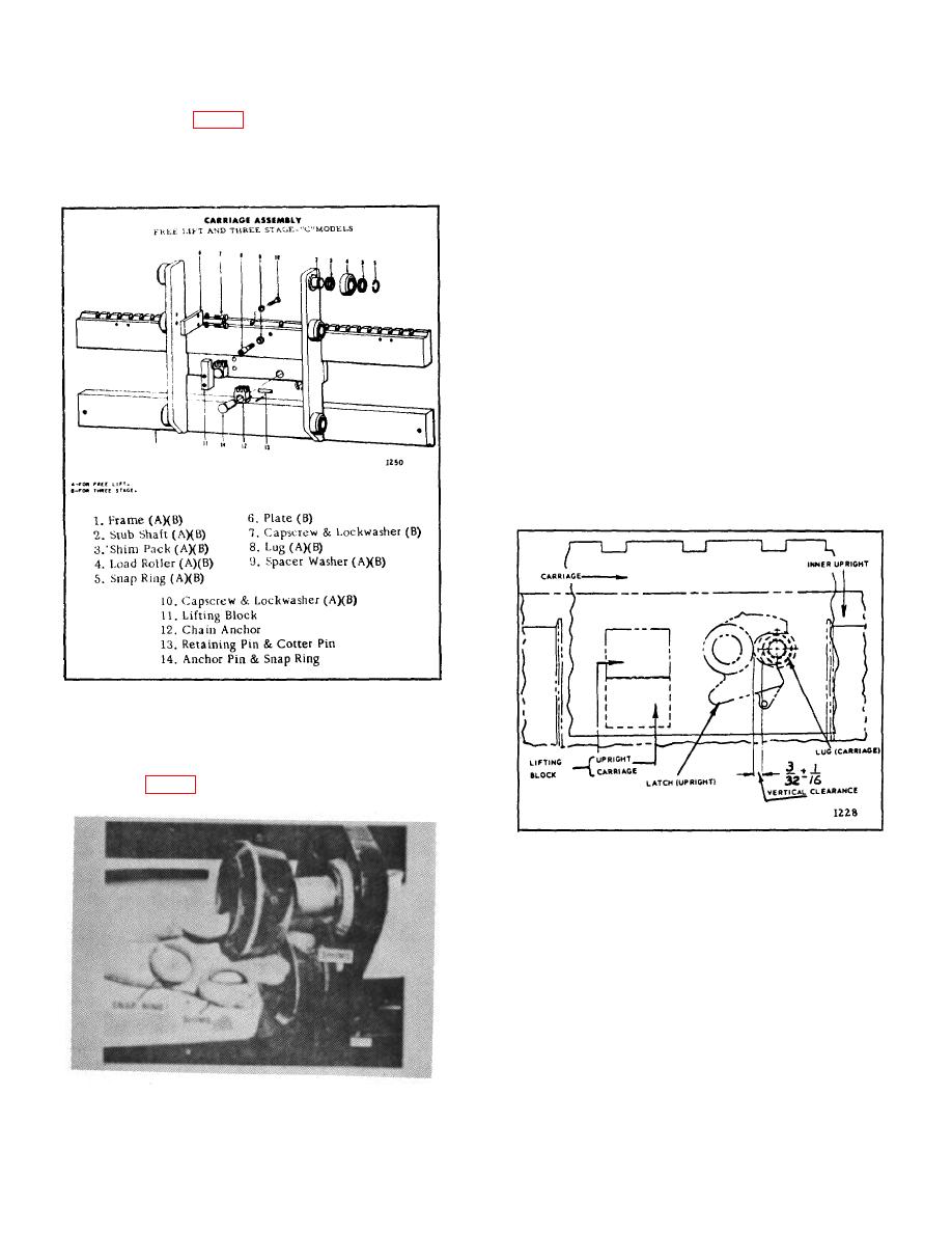
C. DISASSEMBLY (Fig. 3)
3. Remove the remaining rollers.
1. Remove snap ring from one of the stub shafts.
D. ADJUSTING LOAD ROLLERS AND INSTALLATION
Remove the shims next to the load roller.
1. Make sure that the load rollers cannot move
sideways on the stub shafts. If necessary, add shims to
the original shim pack (or pack thickness) to eliminate
clearance between the shims and the retaining snap
ring, at time of installation.
2. Install the carriage using the reverse of the
removal procedure, transposing shims until the carriage
fits in the inner upright as tight as possible and still
permits no-load lowering. Check lug-go-latch clearance.
3. Check and adjust latch clearance as follows:
a. Raise the carriage until the lifting block on
the carriage just makes contact with a similar
block on the inner upright.
b. Measure the clearance as indicated in
Figure 5.
Figure 3.
2. Pull load roller off and note the thickness of the
shim packs. (Fig. 4)
Figure 5.
c. If clearance is more than 5/32 inch or less
than 1/32 inch (desired clearance is 3/32
Figure 4.
B-170
|
|
Privacy Statement - Press Release - Copyright Information. - Contact Us |