 |
|||
|
|
|||
|
Page Title:
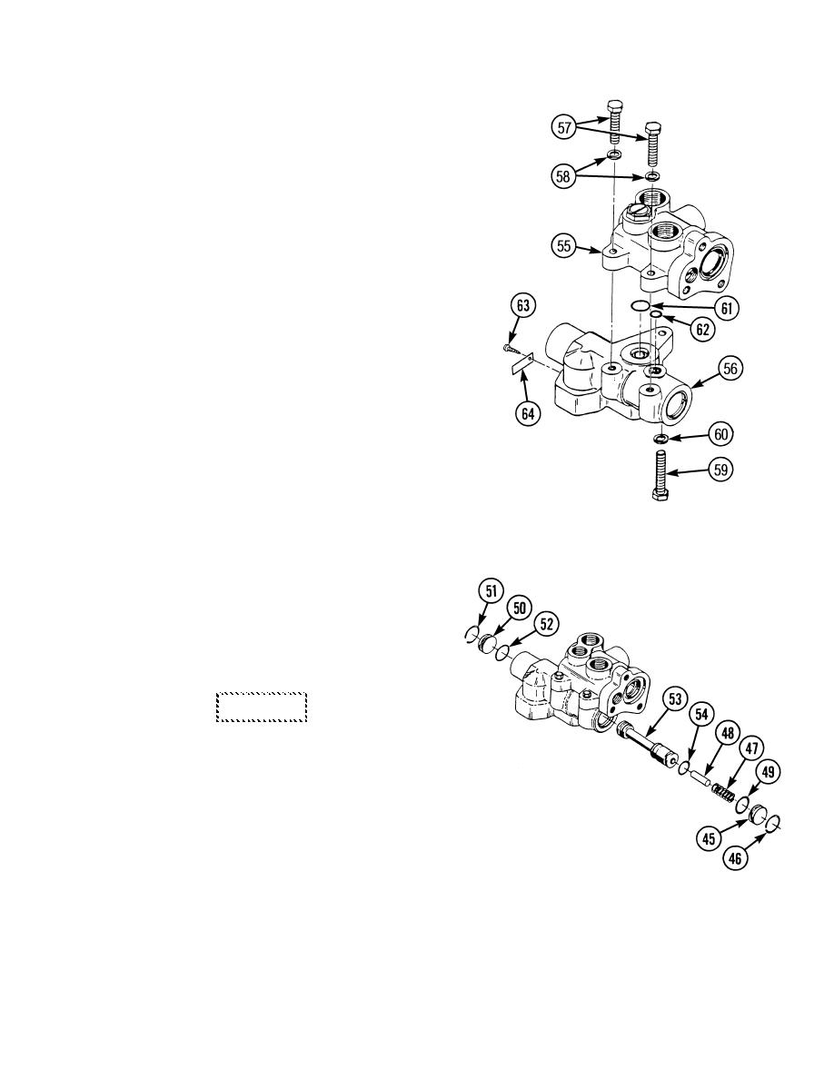
BRAKE CONTROL VALVE REPAIR - continued |
|
||
| ||||||||||
|
|
 TM 10-3930-673-34
d. Assembly.
NOTE
Wipe all sealing surfaces on pump
clean and dry. Apply film of clean
hydraulic oil to all seals as they are
installed.
(1)
Assemble control housing (55) to
charging section (56).
(a)
If removed, install label (64) and
two screws (63) on charging
section (56).
(b)
Install preformed packings (61 and
62) in charging section (56).
(c)
Assemble control housing (55) to
charging section (56).
(d)
Install lockwasher (60) and
screw (59) in control housing (55)
and charging section (56). Tighten
screw to 22 - 27 lb-ft (29.83 -
36.61 Nm).
TR00478
(e)
Install two lockwashers (58) and
screws (57) in control housing (55)
and charging section (56). Tighten
screws to 22 - 27 lb-ft (29.83 - 36.61 Nm).
(2)
Assemble internal parts (1
through 54) of brake control valve.
(a)
Install preformed packing (52) on
plug (50) and install plug with
retaining ring (51).
CAUTION
Use care to prevent damage to lands
on spool and inside bore. Do not
force spool into valve. Failure to
follow this precaution will cause
part damage.
(b)
Install preformed packing (54) on
spool (53). Insert spool into valve
bore. Ensure that spool is oriented
TR00477
correctly. Ensure that spool makes
contact with plug (50) on opposite
side of brake control valve.
(c)
Install stop (48) and spring (47).
(d)
Install preformed packing (49), plug (45), and retaining ring (46).
10-13
|
|
Privacy Statement - Press Release - Copyright Information. - Contact Us |
