 |
|||
|
|
|||
|
Page Title:
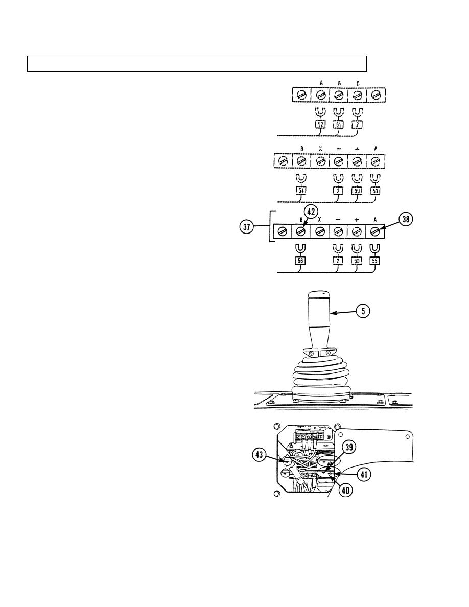
ELECTRIC JOYSTICK ASSEMBLY REPAIR/TEST/ADJUSTMENT - continued |
|
||
| ||||||||||
|
|
 TM 10-3930-673-34
6-7. ELECTRIC JOYSTICK ASSEMBLY REPAIR/TEST/ADJUSTMENT (CONT)
(4)
Measure current flow to lower circuit
board (37). If necessary, adjust
"threshold" and "max out" controls.
(a)
Loosen screw (38) at terminal A of
lower circuit board (37) and
disconnect electrical lead #55.
(b)
Connect positive (+) lead of
multimeter to terminal A of lower
circuit board (37).
(c)
Connect negative () lead of
multimeter to disconnected
electrical lead #55.
(d)
Turn starter switch to the RUN
position but do not start the engine
(TM 10-3930-673-10).
(e)
Slowly move joystick handle (5)
rearward until indicator light (39)
TR01124
just comes on. Multimeter reading
should be between 300 and 340 ma.
NOTE
During Step (f), turn "threshold"
control counterclockwise to lower
multimeter reading, and clockwise
to raise multimeter reading.
(f)
If reading in Step (e) was not within
limits of 300 to 340 ma., adjust
"threshold" control (40) and repeat
Step (e) until multimeter reads
approximately 320 ma.
(g)
Move joystick handle (5) fully
rearward and observe multimeter
reading. Reading should be between
600 and 640 ma.
NOTE
During Step (h), turn "max out"
TR01125
control counterclockwise to lower
multimeter reading, and clockwise
to raise multimeter reading.
6-34
|
|
Privacy Statement - Press Release - Copyright Information. - Contact Us |
