 |
|||
|
|
|||
|
Page Title:
ELECTRIC JOYSTICK ASSEMBLY REPAIR/TEST/ADJUSTMENT - continued |
|
||
| ||||||||||
|
|
 TM 10-3930-673-34
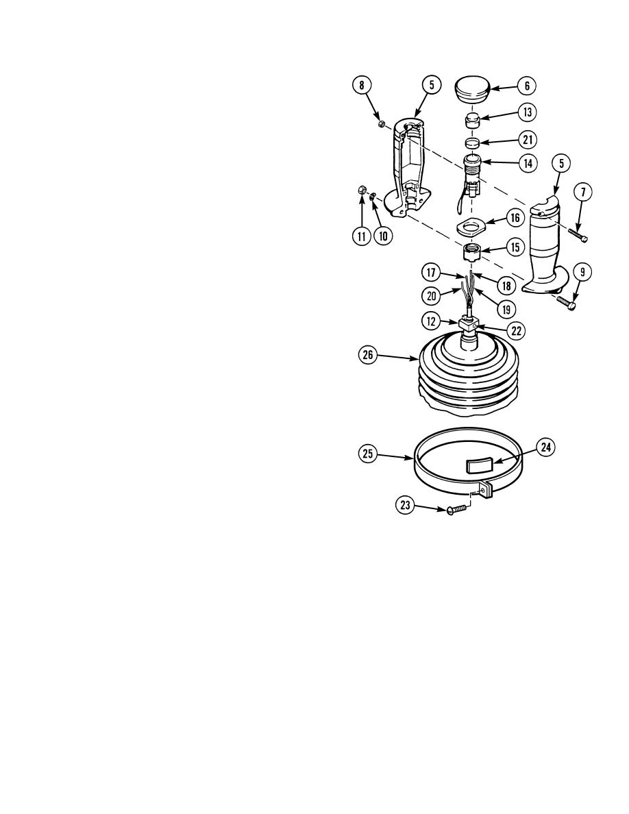
b. Handle Pushbutton Switch Removal.
(1)
Remove parts (6 through 11) and
parts (13 through 16) from handle
sections (5).
(a)
Pull off boot (6) from handle
sections (5).
(b)
Remove two screws (7) and nuts (8)
from top of handle sections (5).
(c)
Remove two screws (9), bowed
washers (10), and nuts (11) at
bottom of handle sections (5).
Discard bowed washers.
(d)
Separate handle sections (5) and
remove them from shaft
coupling (12).
(e)
Remove actuating button (13) from
handle section (5).
(f)
Remove pushbutton switch (14),
nut (15), and flange (16) as an
assembly from handle sections (5).
(2)
Tag, mark, and desolder four
wires (17 through 20) from
pushbutton switch (14) and
disassemble parts (12, 15, 16, and 21
through 26).
(a)
Tag, mark, and desolder four
wires (17 through 20) from
pushbutton switch (14).
TR01119
(b)
Remove nut (15) and flange (16)
from pushbutton switch (14).
(c)
Remove cover (21) from pushbutton switch (14).
(d)
If damaged, loosen set screw (22) and remove shaft coupling (12) and set screw.
(e)
If damaged, remove screw (23), band (24), clamp (25), and boot (26).
c. Inspection.
(1)
Check for loose or disconnected plug (2) at switch (1).
(2)
Check all switches for loose mounting hardware or visible damage.
6-29
|
|
Privacy Statement - Press Release - Copyright Information. - Contact Us |
