 |
|||
|
|
|||
|
Page Title:
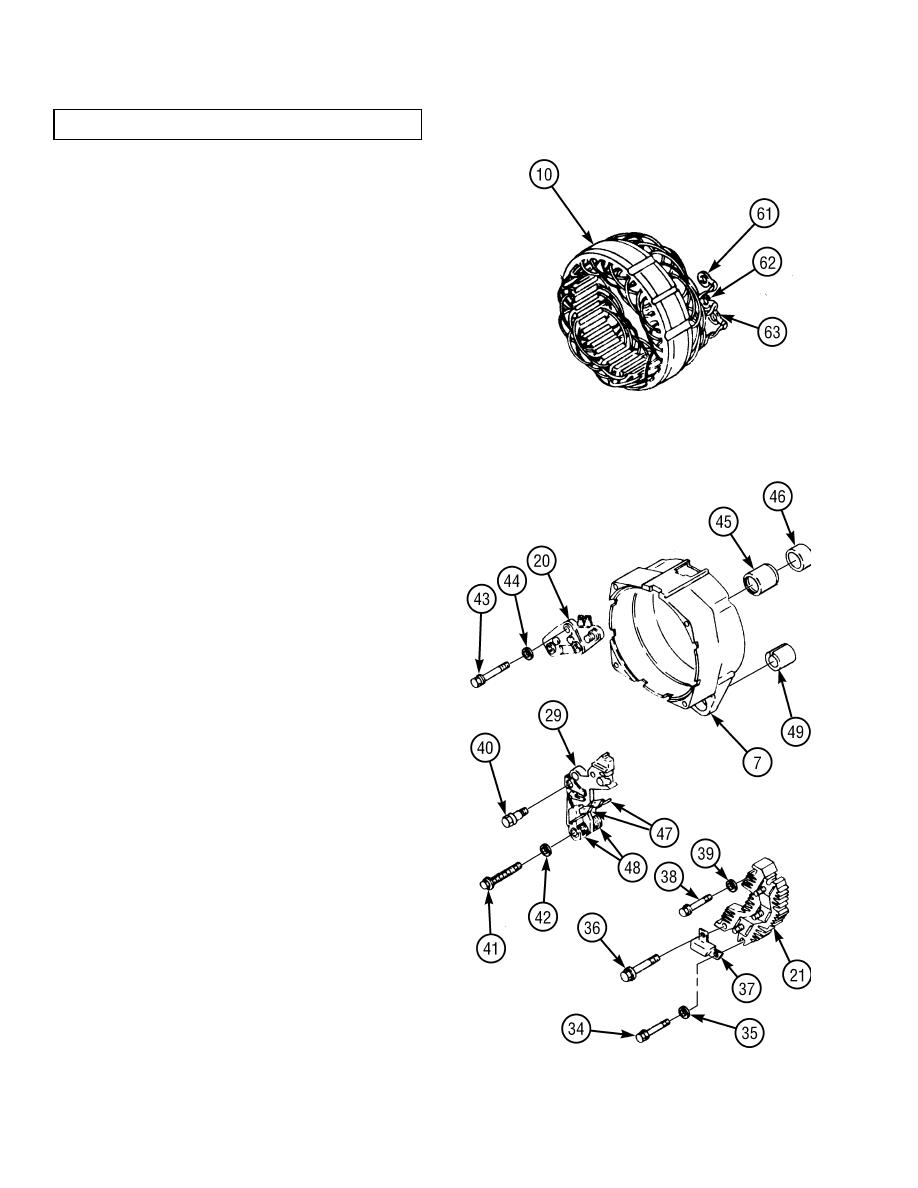
ALTERNATOR REPAIR/TEST - continued |
|
||
| ||||||||||
|
|
 TM 10-3930-673-34
6-3. ALTERNATOR REPAIR/TEST (CONT)
(4)
Test stator assembly (10) for open or
grounded windings.
(a)
Using a multimeter set to ohms, low
scale, measure resistance through stator
windings. Connect multimeter to terminal
clips (61 through 63), from each outside
clip to center clip and then between two
outside clips.
(b)
Measure resistance from each terminal
clip (61 through 63) to stator frame to
check for grounded windings. A low
resistance reading between any terminal
TR01433
clip and stator frame indicates a grounded
winding, and stator (10) must be replaced
as a unit.
e. Assembly.
(1)
Using suitable press, install bushing (49) on
rear frame (7).
(2)
Position two springs (48) and brushes (47) on
brush holder assembly (29).
(3)
Install roller bearing (45) in rear frame (7).
(a)
Pack roller bearing (45) with lubricant.
(b)
Using a suitable press, install bearing (45)
into rear frame (7). Bearing side should
be flush with inside base of frame (7).
(c)
Install cap (46) in rear frame (7).
(4)
Install regulator (20) on rear frame (7) with
washer (44) and screw (43).
(5)
Install brush holder assembly (29) on rear
frame (7) and regulator (20) with washer (42)
and screw (41) and insulated screw (40).
(6)
Install rectifier bridge assembly (21) on rear
frame (7) with washer (39) and screw (38).
(7)
Install capacitor (37) on bridge rectifier
assembly (21) with washer (35), screw (34),
and insulated screw (36).
6-8
|
|
Privacy Statement - Press Release - Copyright Information. - Contact Us |
