 |
|||
|
|
|||
|
Page Title:
TURBOCHARGER ASSEMBLY REPAIR - continued |
|
||
| ||||||||||
|
|
 TM 10-3930-673-34
WARNING
Use care when removing snap and retaining rings. Snap and retaining rings are under
spring tension and can act as projectiles when released and could cause severe eye
injury.
(25)
Remove two inner retaining rings (33) from bore of bearing housing (14). Discard
retaining rings.
(26)
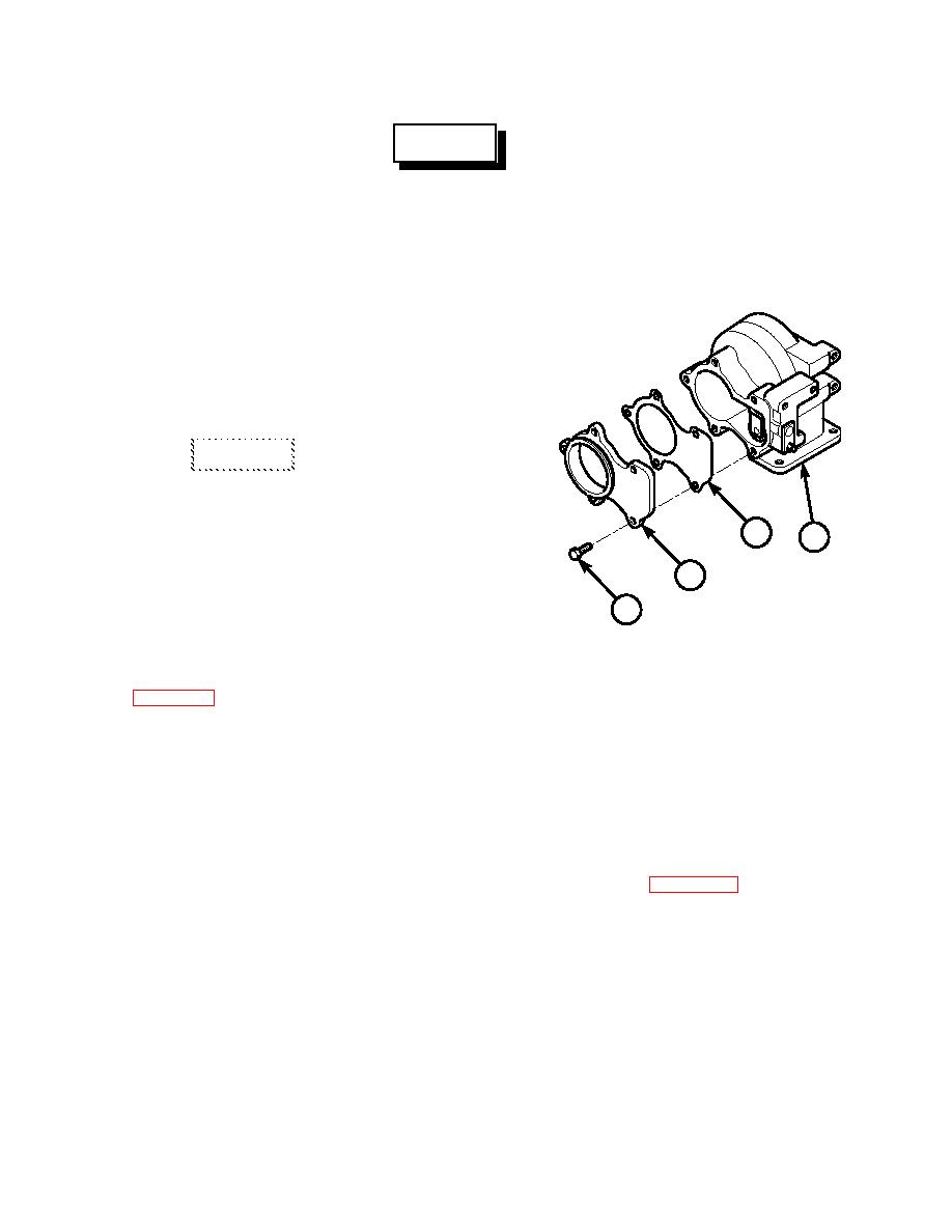
If damaged, remove five screws (34),
adapter (35), and gasket (36) from
turbine housing (1).
b. Cleaning.
CAUTION
Do not use a wire brush on the
compressor wheel. Use of a wire
brush on compressor wheel may
36
1
cause premature component failure.
35
(1)
Use a scraper and medium grit
emery cloth to remove carbon
34
buildup from turbine housing (1).
TR01393
(2)
For general cleaning instructions,
see Cleaning Instructions,
c. Inspection.
(1)
Measure shaft and wheel (19) bearing diameter. Shaft bearing surface minimum
diameter is 0.432 in. (10.972 mm).
(2)
Measure bearing housing (14) bore diameter. Bearing housing bore minimum diameter
is 0.6254 in. (15.885 mm).
(3)
For general inspection instructions, see Inspection Instructions, (Para 2-14).
d. Assembly.
NOTE
Balance marks on shaft and wheel, impeller, thrust collar and oil slinger must be aligned
to make sure rotating parts of turbocharger are properly balanced.
(1)
If removed, install gasket (36), adapter (35), and five screws (34) on turbine
housing (1).
4-25
|
|
Privacy Statement - Press Release - Copyright Information. - Contact Us |
