 |
|||
|
|
|||
|
|
|||
| ||||||||||
|
|
 TM 10-3930-673-34
3-8. CRANKSHAFT REPLACEMENT/REPAIR (CONT)
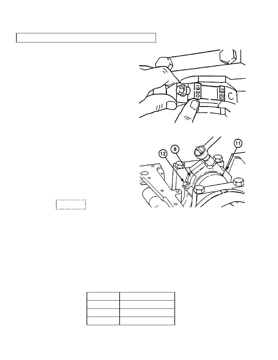
(h)
Remove screws (12) and connecting
rod caps (8).
(i)
Measure plastigage to determine
what size connecting rod bearings to
install.
(j)
Repeat Steps (a) through (i) for the
other five connecting rods.
(6)
Install connecting rod bearings (10
and 11) and caps (7).
(a)
Turn crankshaft (16) until two
connecting rod bearing journals are
bottom center.
(b)
Put upper bearing half (9) on
connecting rod (11) with tab in the
rod groove.
(c)
Put lower bearing half (10) in
connecting rod cap (8) with tab in
cap groove.
(d)
Apply Lubriplate 105 to inside
surfaces of upper and lower bearing
halves (9 and 10).
CAUTION
TR01178
The four digit number stamped on
the connecting rod and the rod cap
must match and be facing the oil
cooler side of the engine. Connecting
rod and cap are machined as a set
and must be kept that way. Failure
to install matched sets could result
in premature engine damage.
(e)
Pull piston and connecting rod assembly against crankshaft journal and install bearing
cap (8) and screws (12). Tighten screws finger tight.
(f)
The connecting rod screws (12) must be tightened evenly in a series of three steps. The torque
value for each step is shown in the following chart.
Step
Torque Value
1
26 lb-ft (35.25 Nm)
2
50 lb-ft (67.79 Nm)
3
73 lb-ft (98.97 Nm)
3-70
|
|
Privacy Statement - Press Release - Copyright Information. - Contact Us |
