 |
|||
|
|
|||
|
|
|||
| ||||||||||
|
|
 TM 10-3930-673-34
(2)
Remove drive shaft assembly (1) from engine dampener (7).
(a)
Remove three screws (8) from engine coupling (9).
(b)
Temporarily install two screws (8) removed in Step (2)(a) above in two jacking holes (10) of
engine coupling (9).
(c)
Tighten two screws (8) evenly until shaft assembly (1) and engine coupling (9) separates from
engine dampener (7).
(d)
Remove coupling (9) and shaft assembly (1) from vehicle as an assembly.
NOTE
Note routing of engine and STE/ICE
wiring harnesses before removal.
(3)
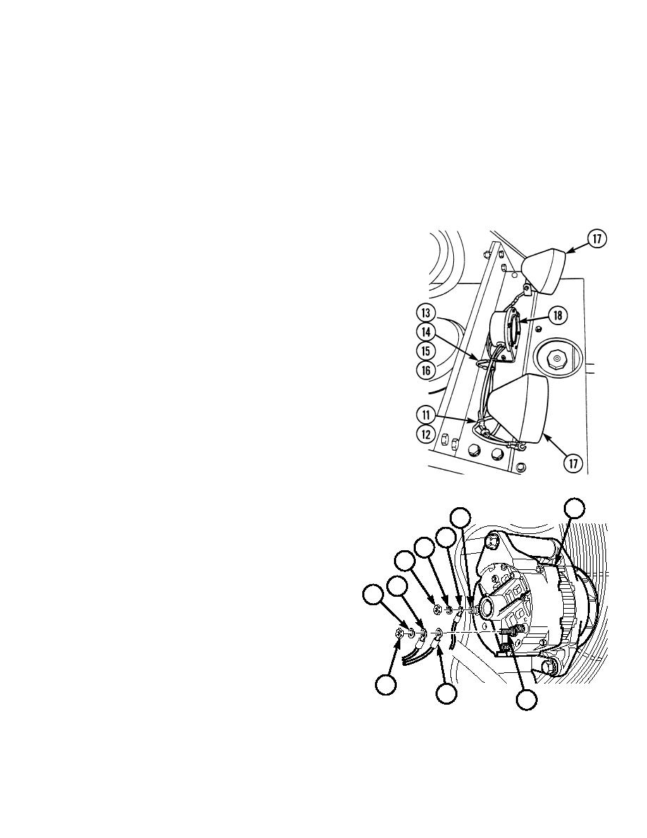
Tag, mark, and disconnect engine
and STE/ICE wiring connections.
(a)
Tag, mark, and disconnect electrical
connections (11 through 16) from
rear flood lights (17) and back-up
alarm (18).
TR01326
(b)
Tag and mark electrical wires
24
no. N (19) and no. 60 (20). Remove
28
nut (21), lockwasher (22), electrical
25
wires no. N, and no. 60 from "BAT"
27
terminal (23) on alternator (24).
26
Discard lockwasher.
19
(c)
Tag and mark electrical wire
22
no. P (25). Remove nut (26),
lockwasher (27), and electrical wire
no. P from "GRD" terminal (28) on
alternator (24). Discard
lockwasher.
21
20
23
TR01327
3-5
|
|
Privacy Statement - Press Release - Copyright Information. - Contact Us |
