 |
|||
|
|
|||
|
Page Title:
ELECTRIC JOYSTICK CONTROL DOES NOT OPERATE - continued |
|
||
| ||||||||||
|
|
 TM 10-3930-673-20-1
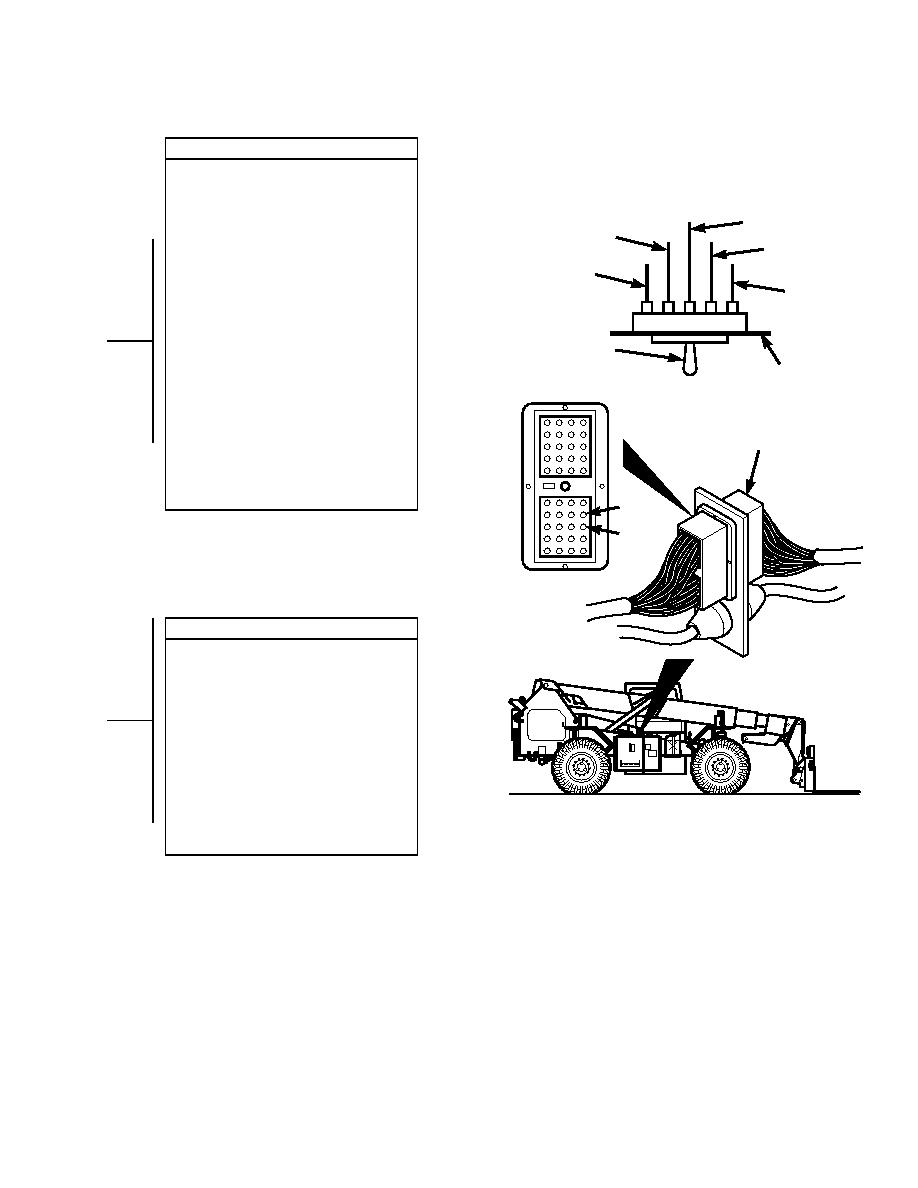
VOLTAGE TEST
(1) Set multimeter to volts dc.
(2) Connect multimeter positive lead (+) to
fork leveler mode switch where wire 57
and 58 connect.
WIRE 59
(3) Connect multimeter negative lead () to
WIRE 58
WIRE 64
known good ground.
(4) Connect negative battery cable to
WIRE 57
negative side of battery (Para 8-42).
WIRE 65
(5) Turn engine start switch to ON position,
BUT DO NOT START ENGINE
(TM 10-3930-673-10).
(6) Turn fork leveler mode switch to
F UTOMATIC
A
MANUAL position
OS K LEVEL
R
(TM 10-3930-673-10).
P ASH
D
WITCH
(a) If voltage is present, go to Step 9
ANEL
of this fault.
(b) If voltage is not present, replace
fork leveler mode switch
CONNECTOR J1
(Para 8-20).
(7) Turn engine start switch to OFF
position (TM 10-3930-673-10).
(8) Disconnect negative battery cable from
negative side of battery (Para 8-42).
P1-34
P1-33
CONNECTOR P1
CONTINUITY TEST
(1) Set multimeter to ohms.
(2) Disconnect connector J1 from
connector P1.
(3) Connect multimeter positive lead (+) to
fork leveler mode switch where wire 57
and 58 connect.
(4) Connect multimeter negative lead () to
main connector pin 33 and 34 for
appropriate wire.
(a) If continuity is present, go to
Step 10 of this fault.
TR01660
(b) If continuity is not present, repair
faulty wire and/or connector
(Para 8-48).
2-501
|
|
Privacy Statement - Press Release - Copyright Information. - Contact Us |
