 |
|||
|
|
|||
|
Page Title:
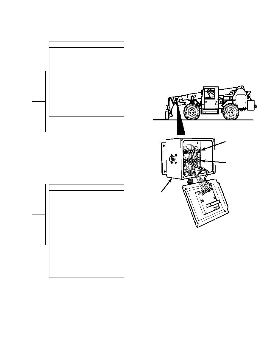
ELECTRIC JOYSTICK CONTROL DOES NOT OPERATE - continued |
|
||
| ||||||||||
|
|
 TM 10-3930-673-20-1
CONTINUITY TEST
(1) Set multimeter to ohms.
(2) Disconnect connector P3 from
connector J3.
(3) Connect multimeter positive lead (+) to
electrical junction box terminal board
pin for appropriate function.
(4) Connect multimeter negative lead () to
boom connector pin for appropriate
function.
(a) If continuity is present, go to Step 7
of this fault.
(b) If continuity is not present, repair
faulty wire and/or connector
(Para 8-50).
(5) Connect connector J3 to connector P3.
B
TERMINAL
T OARD
B1
B
TERMINAL
T OARD
B2
VOLTAGE TEST
E
BOOM
(1) Set multimeter to volts dc.
(2) Connect multimeter positive lead (+) to
BLECTRICAL
electrical junction box TB1-4 or TB1-5
OX
for appropriate function.
(3) Connect multimeter negative lead () to
known good ground.
(4) Connect negative battery cable to
negative side of battery (Para 8-42).
(5) Turn engine start switch to ON position,
TR01659
BUT DO NOT START ENGINE
(TM 10-3930-673-10).
(a) If voltage is present, go to Step 8
of this fault.
(b) If voltage is not present, repair wire
53 or 54 (Para 8-50).
(6) Turn engine start switch to OFF
position (TM 10-3930-673-10).
(7) Disconnect negative battery cable from
negative side of battery (Para 8-42).
2-499
|
|
Privacy Statement - Press Release - Copyright Information. - Contact Us |
