 |
|||
|
|
|||
|
Page Title:
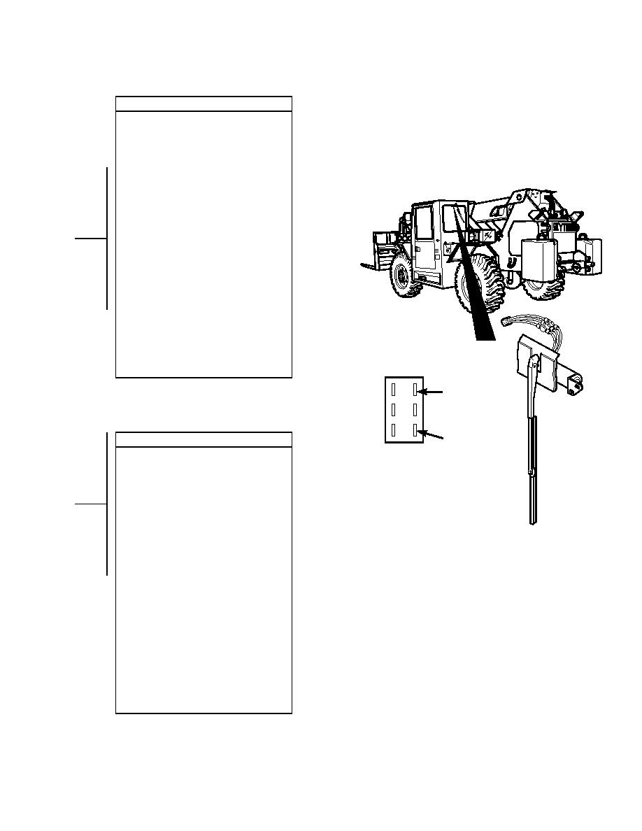
REAR WINDSHIELD WIPERS DO NOT OPERATE - continued |
|
||
| ||||||||||
|
|
 TM 10-3930-673-20-1
VOLTAGE CHECK
(1) Set multimeter to volts dc.
(2) Remove rear wiper motor from vehicle
(Para 17-3).
(3) Connect multimeter positive lead (+) to
wire 34 where wire 34 connects to rear
wiper motor.
(4) Connect multimeter negative lead () to
known good ground.
(5) Connect negative battery cable to
negative side of battery (Para 8-44).
(6) Turn engine start switch to ON position,
BUT DO NOT START ENGINE
(TM 10-3930-673-10).
(7) Turn rear wiper switch to LO position
(TM 10-3930-673-10).
(a) If 24 vdc is present, go to Step 5 of
this fault.
(b) If 24 vdc is not present, repair
wire 34 (Para 8-48).
(8) Turn rear wiper switch to OFF position
(TM 10-3930-673-10).
(9) Turn engine start switch to OFF
position (TM 10-3930-673-10).
(10) Disconnect negative battery cable
(Para 8-44).
T
WIRE 33
O MOTOR
T
WIRE 34
VOLTAGE CHECK
O MOTOR
RES R WIPER
A
(1) Set multimeter to volts dc.
WITCH
(2) Connect multimeter positive lead (+) to
wire 33 where wire 33 connects to rear
wiper motor.
(3) Connect multimeter negative lead () to
known good ground.
(4) Connect negative battery cable to
negative side of battery (Para 8-44).
(5) Turn engine start switch to ON position,
BUT DO NOT START ENGINE
(TM 10-3930-673-10).
(6) Turn rear wiper switch to HI position
(TM 10-3930-673-10).
TR01157
(a) If 24 vdc is present, replace rear
wiper motor (Para 17-3).
(b) If 24 vdc is not present, repair
wire 33 (Para 8-48).
(7) Turn rear wiper switch to OFF position
(TM 10-3930-673-10).
(8) Turn engine start switch to OFF
position (TM 10-3930-673-10).
(9) Install rear wiper motor (Para 17-3).
(10) Install battery cover (Para 8-42).
(11) Install four screws to secure left-hand
instrument panel.
2-421
|
|
Privacy Statement - Press Release - Copyright Information. - Contact Us |
