 |
|||
|
|
|||
|
Page Title:
BLACKOUT STOPLIGHTS DO NOT OPERATE - continued |
|
||
| ||||||||||
|
|
 TM 10-3930-673-20-1
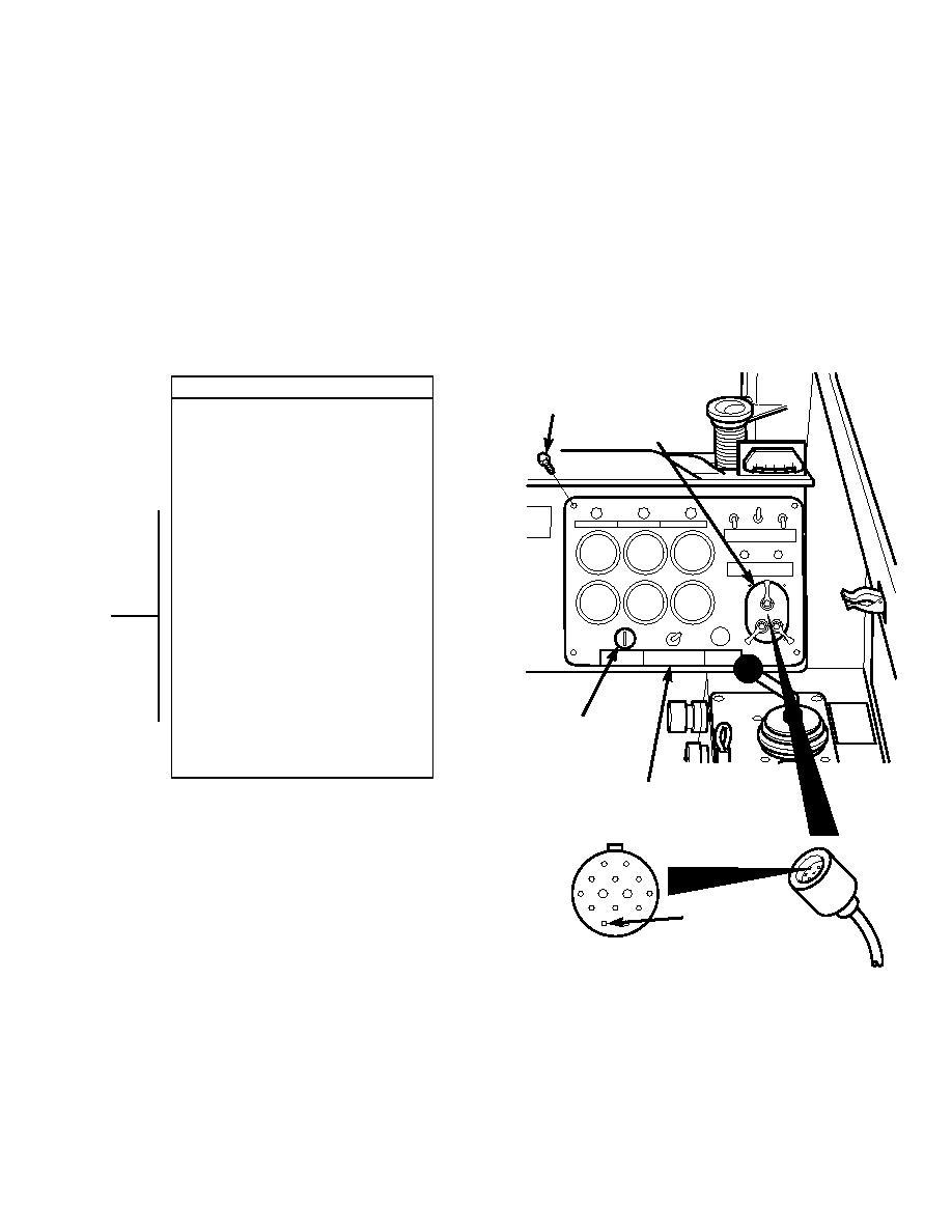
VOLTAGE TEST
SCREW
(1) Remove four screws and instrument
BLACKOUT
panel.
LIGHT SWITCH
(2) Lift instrument panel out to remove
connector J3 from blackout light switch.
(3) Set multimeter to volts dc.
(4) Connect multimeter positive lead (+) to
connector J3-F (wire 40).
(5) Connect multimeter negative lead () to
known good ground.
(6) Connect negative battery cable to
negative side of battery (Para 8-42).
(7) Turn engine start switch to ON position,
BUT DO NOT START ENGINE
(TM 10-3930-673-10).
(a) If 24 vdc is present, go to Step 11
of this fault.
(b) If 24 vdc is not present, repair
wire 40 (Para 8-48).
(8) Turn engine start switch to OFF
position, (TM 10-3930-673-10).
(9) Disconnect negative battery cable from
ENGINE START
negative side of battery (Para 8-42).
SWITCH
(10) Connect connector J3 to blackout light
switch.
INSTRUMENT
PANEL
J3-F
CONNECTOR J3
TR01646
2-355
|
|
Privacy Statement - Press Release - Copyright Information. - Contact Us |
