 |
|||
|
|
|||
|
Page Title:
LEFT TURN SIGNAL DOES NOT OPERATE - continued |
|
||
| ||||||||||
|
|
 TM 10-3930-673-20-1
Remove rings bracelets watches, necklaces, and any other jewelry before working around vehicle. Jewelry can catch on
equipment and cause injury or short across electrical circuit and cause severe burns or electrical shock.
Battery acid is harmful to skin and eyes. Always wear eye protection when working with batteries.
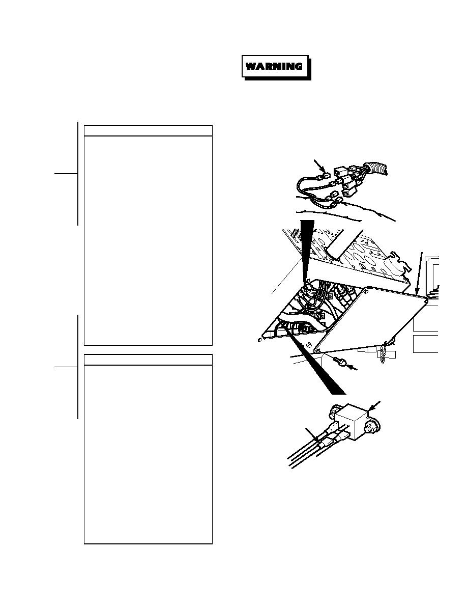
VOLTAGE TEST
(1) Remove battery cover (Para 8-42).
(2) Disconnect negative battery cable from
WIRE 25
negative side of battery (Para 8-42).
(3) Remove four screws and access panel.
(4) Set multimeter to volts dc.
(5) Connect multimeter positive lead (+) to
turn signal flasher male blade
connector where wire 25 connects.
(6) Connect multimeter negative lead () to
known good ground.
(7) Connect negative battery cable to
negative side of battery (Para 8-42).
(8) Turn engine start switch to ON position,
ACCESS
P
BUT DO NOT START ENGINE
ANEL
(TM 10-3930-673-10).
(9) Turn ON left turn signal
(TM 10-3930-673-10).
(a) If 24 vdc is present, go to Step 3 of
this fault.
(b) If 24 vdc is not present, replace
turn signal flasher (Para 8-24).
(10) Turn OFF left turn signal
(TM 10-3930-673-10).
(11) Turn engine start switch to OFF
position (TM 10-3930-673-10).
(12) Disconnect negative battery cable from
negative side of battery (Para 8-42).
VOLTAGE TEST
SCREW
(1) Set multimeter to volts dc.
(2) Connect multimeter positive lead (+) to
turn signal switch where wire 25
TURN SIGNAL
F
connects.
LASHER
(3) Connect multimeter negative lead () to
known good ground.
(4) Connect negative battery cable to
WIRE 25
negative side of battery (Para 8-42).
(5) Turn engine start switch to ON position,
BUT DO NOT START ENGINE
(TM 10-3930-673-10).
(6) Turn ON left turn signal
(TM 10-3930-673-10).
(a) If 24 vdc is present, go to Step 4 of
TR01718
this fault.
(b) If 24 vdc is not present, repair
wire 25 (Para 8-48).
(7) Turn OFF left turn signal
(TM 10-3930-673-10).
(8) Turn engine start switch to OFF
position (TM 10-3930-673-10).
(9) Disconnect negative battery cable from
negative side of battery (Para 8-42).
2-215
|
|
Privacy Statement - Press Release - Copyright Information. - Contact Us |
