 |
|||
|
|
|||
|
Page Title:
VDC CIRCUITS DO NOT OPERATE - continued |
|
||
| ||||||||||
|
|
 TM 10-3930-673-20-1
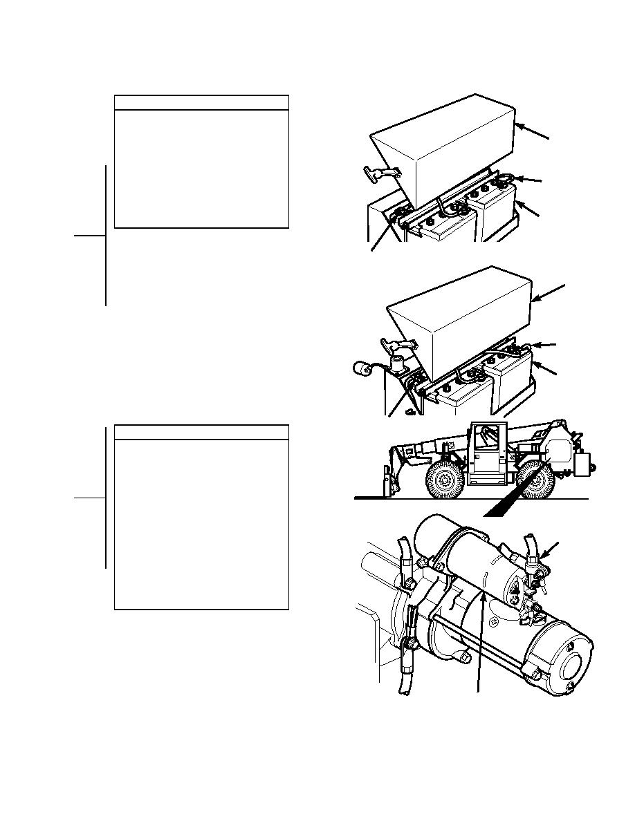
VOLTAGE TEST
(1) Remove battery cover (Para 8-42).
(2) Set multimeter to volts dc.
(3) Connect multimeter negative lead () to
COVER
known good ground.
(4) Connect multimeter positive lead (+) to
NEGATIVE
B
positive lead of battery.
(a) If 24 vdc is present, go to Step 3 of
ACTERY
T
this fault.
ABLE
(b) If 24 vdc is not present, service
battery or replace battery
BATTERY
(Para 8-42).
POSITIVE LEAD
COVER
NEGATIVE
B
ACTERY
T
ABLE
BATTERY
POSITIVE LEAD
VOLTAGE TEST
(1) Disconnect negative battery cable from
negative side of battery (Para 8-44).
(2) Set multimeter to volts dc.
(3) Connect multimeter positive lead (+) to
starter motor solenoid where positive
battery cable connects.
(4) Connect multimeter negative lead () to
BOSITIVE
P
known good ground.
ACTERY
T
(5) Connect negative battery cable to
ABLE
negative side of battery (Para 8-44).
(a) If 24 vdc is present, go to Step 4 of
this fault.
(b) If 24 vdc is not present, repair
battery cable (Para 8-44).
(6) Disconnect negative battery cable from
negative side of battery (Para 8-44).
STARTER SOLENOID
TR01083
2-39
|
|
Privacy Statement - Press Release - Copyright Information. - Contact Us |
