 |
|||
|
|
|||
|
|
|||
| ||||||||||
|
|
 TM 10-3930-673-20-1
2-14.1. STE/ICE-R VEHICLE SYSTEM DIAGNOSTIC CHECK (CONT)
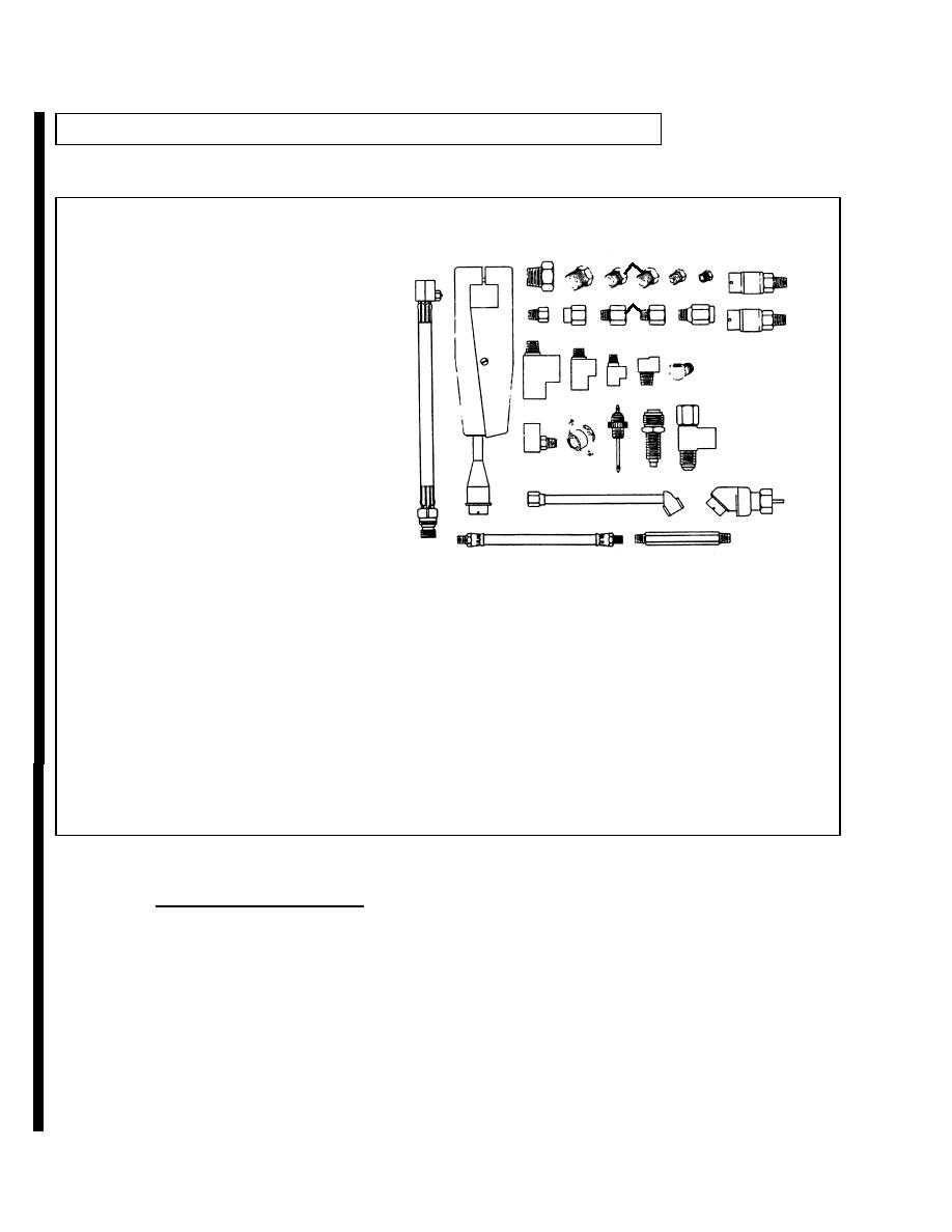
TRANSDUCER KIT CONTENTS
3
4
1.
Hose Assembly, TK10
2
5
7
6
1
2.
Prod, Test TK11
8
12
11
3.
Reducer, Pipe TK12
10
9
13
4.
Reducer, Pipe TK13
14
15 16 17
5.
Reducer, Pipe TK14
18
6.
Plug, Pipe TK15
7.
Plug, Pipe TK16
21 22 23
8.
Transducer (Blue) 0 to 1,000 psi TK17
20
19
9.
Adapter, Straight TK18
10.
Reducer, Pipe TK19
11.
Reducer, Pipe TK20
25
24
12.
Dampener, Fluid TK21
13.
Transducer (Red) -30 in. he to 25 psi TK22
27
26
14.
Tee, Pipe TK23
15.
Tee, Pipe TK24
16.
Tee, TK25
17.
Elbow, Pipe TK26
18.
Elbow, Pipe TK27
19.
Tee, Pipe to Tube TK28
20.
Adapter, Connector TK29
21.
Adapter, Connector TK30
22.
Adapter, Speedometer, TK31
23.
Tee, Pipe to Fuel Line TK32
24.
Chuck, Inflating TK33
25.
Tachometer, Pulse TK34
26.
Hose Assembly TK35
27.
Nipple, Pipe TK36
Refer to the manual provided with the STE/ICE-R kit for description and operation of the VTM and the TK.
(c) STE/ICE-R Testing Procedures. The vehicle test procedures consist of two test sequences; GO-Chain
Sequences and NO-GO-Chain Sequences. A GO-Chain sequence is a logical sequence of tests performed to determine the
general condition of the vehicle. If the vehicle fails any of the GO-Chain tests, the test will direct the user to a specific NO-GO
test for further testing. The NO-GO tests are used to isolate what is wrong with the vehicle.
The GO and NO-GO-Chain Sequences are presented as an illustrated flowchart with test branching controlled by YES and NO
decisions. Generally, a YES determination leads to the next test; a NO determination leads to NO-GO testing and corrective
action.
When the VTM interfaces with the vehicle through the Diagnostic Connector Assembly (DCA) the test is titled
DCA Mode Testing. If the VTM interfaces with the vehicle through the use of the transducer kit (TK), the test is
titled TK Mode Testing. The DCA and TK testing modes can be used at the same time.
Change 1
|
|
Privacy Statement - Press Release - Copyright Information. - Contact Us |
