| |
TM 10-3930-671-24
5.
Check hydraulic system relief pressure setting at
full throttle. Accelerate the engine to no-load
governed speed (full throttle), and hold at this
speed while obtaining the pressure readings.
6.
Move the tilt control lever to full back (or forward)
tilt relief position. Hold tilt control in relief
position until pressure reading is obtained, and
then release.
NOTE
Do not operate system over relief any
longer than required to read the
pressure gauge.
Hydraulic System Relief Pressure
Specifications
GPX 25E
2600-2700 psi
Reference Section 2. 1, Service Specifications.
Relief Pressure Adjustment
NOTE
If adjustment is necessary, do not
exceed the relief pressure setting
specified for the truck model capacity
rating. Changing the pressure will
not increase lifting capacity or lifting
speed.
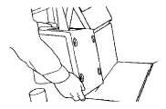
1.
Remove the valve cover from the seat support
plate for access to the relief valve adjustment
screws on the main valve.
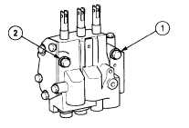
2.
The main hydraulic system relief (1) and aux
relief (2) valve adjustment screws are located on
the upper front side of the main valve.
To adjust, loosen the lock nut, reset and tighten lock
nut. Turn adjustment screw clockwise (CW) to increase
pressure. Turn counterclockwise (CCW) to decrease
pressure.
3.
If pressure relief valve needs to be adjusted,
loosen the lock nut, hold the control lever in relief
position, and turn the relief pressure adjustment
screw until pressure gauge reads the correct
relief pressure setting. Tighten the lock nut.
4.
IMPORTANT - Recheck the relief pressure
setting. With engine running at full throttle, move
the control lever to relief position and read the
pressure gauge. This is to verify that relief
pressure setting has not been changed during
the tightening of the locknut.
5.
If pressure setting is not correct, repeat the
adjustment procedure.
6.
When
relief
pressure
setting
is
correct,
disconnect the pressure gauge. Put the cap on
the quick disconnect fitting. Install the cover
enclosing main valve.
7.
Close
the
engine
compartment,
remove
blocking, and lower drive wheels to the floor.
This completes the procedure for checking and adjusting
main hydraulic relief pressure.
F-456
|