| |
TM 10-3930-671-24
Brake & Inching Circuit
TA18 Transaxle
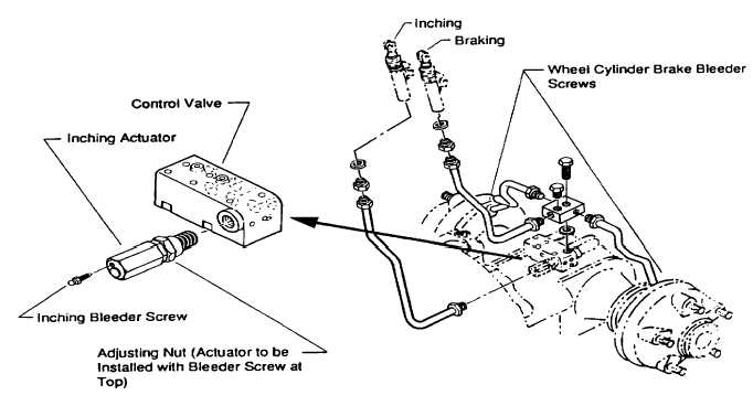
Figure 2. Brake & Inching Circuit Installation, with View of Inching Actuator
4.
Inching circuit bleeder screw is installed in the
end of inching actuator (slave cylinder) on
control valve on transaxle, adjacent to inching
control line. See Figure 2.
NOTE
Inching actuator housing is designed to be
adjustable for positioning the bleeder screw at
the top, using the adjusting nut. To adjust,
loosen adjusting nut, rotate actuator to place
bleeder screw at top, then tighten nut to lock
actuator in place.
Pressure Bleeding Procedure
"Bottom Up" Bleeding With Pressure Bleeder
1.
Inching bleeder screw closed.
2.
Brake bleeder screws closed.
3.
Remove cap from brake fluid reservoir.
4.
Connect inching filler hose to inching bleeder
screw and open bleeder screw.
5.
Wait until brake fluid reservoir is 50% full.
6.
Pump inching (left) pedal 5-10 strokes (with
quick return strokes and 1-2 second intervals
between strokes) while filling.
7.
Tighten inching bleeder screw after reservoir is
75% full.
8.
Install brake filler hose on right-side brake
bleeder screw.
9.
Install brake drain overflow hose on left-side
brake bleeder screw.
10.
Loosen both brake bleeder screws.
11.
Fill brake lines (fluid will drain from reservoir
after Step 10 until Step 11 is started).
12.
Wait until a steady flow is achieved from left
brake bleed drain line with no air bubbles.
13.
Close left-side brake bleeder screw.
14.
Wait until reservoir fluid level starts to rise.
15.
Stroke brake (right) pedal 5-10 times with quick
return strokes and 1-2 second intervals between
strokes.
16.
Close right-side brake bleeder screw.
17.
Remove filler hoses.
18.
Install cap on brake fluid reservoir.
F-397
|

