| |
TM 10-3930-671-24
Brake & Inching Pedal Adjustment (Cont’d)
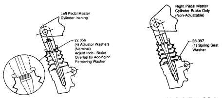
Figure 2. Left-Hand Pedal - Inching Master Cylinder Figure 3. Right-Hand Pedal - Brake Master Cylinder
Inching/Brake Overlap Adjustment
1.
Be sure there is no entrapped air in system. Bleed system thoroughly.
2.
After bleeding system, inching system may be adjusted from nominal by adding or removing adjustor washers
from inching push rod assembly.
NOTE
The nominal or standard installation for adjustor washers on inching pedal is 4 washers (0.040 in. nominal
thickness each).
3.
To increase overlap (reduce truck rollback and increase inching sensitivity, i.e. reduce pedal stroke between
transmission disengagement and brake application): Remove one (1) washer; test truck for inch-brake operation.
Additional washers may be removed, one at a time, to achieve desired inching-to-braking response. All washers
may be removed if required.
NOTE
Excessive overlap will cause transmission overheating and brake wear because transmission will not be
sufficiently disengaged as brakes are applied.
4.
To decrease overlap (decrease inching-to-braking response or sensitivity): Add one (1) washer; test truck for
inch-brake operation. Additional washers may be added, one at a time, while testing to achieve desired inching-to-
braking response. Four (4) washers total max.
Pedal Up Stop (Freeplay) Adjustment
Adjust pedal height such that when pedal is fully returned, brake and inching master cylinders are not engaged. Inching
pedal must have .125-.375 in. (3.2-9.5 mm) freeplay at foot pad.
NOTE
The standard position for the stop screw is with the head and locknut installed on the top (outer) side of
bracket. If 0.25-inch nominal freeplay cannot be achieved, adjusting bolt may be installed from opposite
side.
F-391
|