| |
TM 10-3930-671-24
7.6. TA18 Transaxle
Description and Operation........................................................................................ F-345
Specifications ........................................................................................................... F-346
TA 18 Service Maintenance ..................................................................................... F-348
General Arrangement............................................................................................... F-350
Parts Nomenclature.................................................................................................. F-351
Transaxle Overhaul .................................................................................................. F-359
Service Brake Adjustment ........................................................................................ F-377
Description and Operation
Refer to Section 2.1, Service Specifications for TA-18
Clark Model TA18 transaxle assembly includes:
• Torque converter
• Single-speed forward and reverse power shift
transmission with integral differential and drive axle
• Full-floating straight drive axle-drum-and shoe brakes
• Gear-driven pump drive
• Electric shift control, hydraulic inching control
Powerflow is from torque converter turbine to turbine
(clutch) shaft and gears then thru either forward gear or
reverse idler shaft to output gear mounted on final drive
pinion shaft.
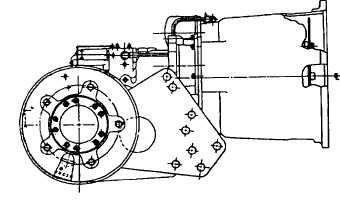
Transmission and differential housed in one-piece
transmission case. Torque converter housing joined to
transmission case through an adaptor (or spacer) plate.
Adaptor plate holds converter stator support and reverse
idler outer bearing.
Pump drive driven by converter impeller hub gear
through idler gear to pump gear mounted on charging
pump shaft.
Final drive pinion gear shaft mounted in tapered roller
bearings at both ends in transmission case, and adjusted
for mounting distance and ring and pinion gear contact
by shim pack installed behind inner tapered roller bearing
cup at pinion gear in transmission case. Pinion shaft
bearing preload is adjusted with shims behind outer
bearing cone on pinion shaft.
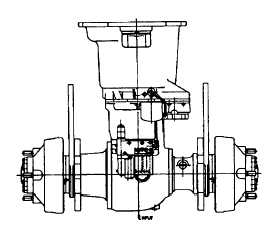
Final drive ring gear bolted to differential carrier.
Differential supported by opposed tapered roller bearings
mounted on inner ends of wheel end housings, which are
bolted to openings in transmission case at the sides of
the differential. Differential bearing preload and ring gear
clearance (backlash) is maintained by shims placed
behind differential bearing cones on wheel end housings.
Adjustment of differential bearing preload or ring gear
backlash requires trial assembly, checking, and
disassembly of wheel end housings until correct
adjustment is obtained.
Drive axle wheel hubs/brake drums supported by double
tapered roller bearings on outer end of wheel end
housings. Drive axle shaft flanges bolted to wheel hubs
and full-floating in differential. Service brake backing
plates bolted to mounting flanges on wheel end
housings. Wheel bearings lubricated from transaxle
sump.
Control valve mounted on pad at top of transmission
case. Oil from charging pump flows thru filter and
pressure regulator to control valve thru external oil
supply
F-345
|