| |
TM 10-3930-671-24
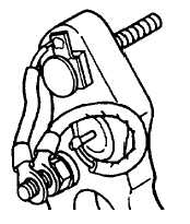
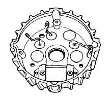
Figure 59 shows the stator tap lead terminal placed over
the stator terminal bolt, inserted through a square
molded insulator in the heat sink.
FIGURE NO. 59.
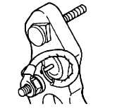
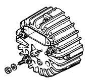
Figure 60 shows assembly of ground terminal bolt and
insulators.
FIGURE NO. 60.
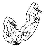
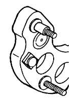
In Figure 61, note insulating washers over output and
ground terminal bolts. The fiber washer for the stator
terminal is placed over the plastic insulating sleeve. Both
are placed over the stator terminal bolt (Figure No. 62).
FIGURE NO. 61.
FIGURE NO. 62.
Apply a thin layer of silicon grease to one side of the
three, mica discs before they are placed in the recessed
area inside the rear housing (Figure No. 63)
FIGURE NO. 63.
Carefully slide heat sink into rear housing, guiding
terminal bolts through the casting. Make certain that all
insulating washers are properly positioned. Install
external insulating washers on output and stator bolts,
follow with flat washers, lockwashers and nuts. The
ground terminal bolt is a metal to metal contact, requiring
a lockwasher and nut to secure connection (Figure No.
64).
FIGURE NO. 64.
F-295
|