| |
TM 10-3930-671-24
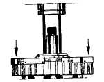
Support bottom of rotor on suitable press, using driver
that contacts inner bearing race, press assembled front
housing and bearing on rotor shaft. Use only sufficient
pressure to seat bearing on shoulder of shaft (Figure No.
53).
FIGURE NO. 53.
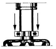
INSTALLATION OF REAR BEARING - Support front
rotor shaft in press, using drive that contacts inner race,
press rear bearing on shaft uo to the shoulder (Figure
No. 54).
FIGURE NO. 54.
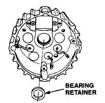
Install new rear bearing retainer in rear bearing cavity
(Figure No. 55).
FIGURE NO. 55.
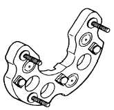
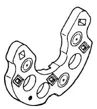
ASSEMBLE HEAT SINK TO REAR HOUSING - The
positive rectifier diode heat sink is electrically insulated
from the rear housing by fiber insulators and three mica
disc insulators. The carriage bolts used for stator and
ground terminals are insulated from the heat sink. The
1/4" output terminal bolt is a metal to metal contact with
the positive heat sink (Figure No. 56).
FIGURE NO. 56.
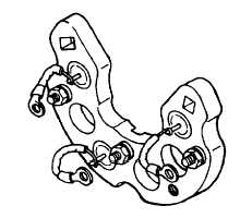
Place each diode terminal screw through a square
molded insulator, position in recess of heat sink (Figure
No. 57). Place fiber insulating washer, flat steel washer,
lockwasher and nut over each screw, tighten securely
(Figure No..58).
FIGURE NO. 57.
FIGURE NO. 58.
F-294
|