| |
TM 10-3930-671-24
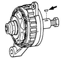
2.
Number 5 Woodruff key may be removed by
replacing
pulley
nut
oh
rotor
shaft,
with
screwdriver wedged between Woodruff key and
nut, pry downward to release Woodruff key from
shaft (Figure No. 45).
FIGURE NO. 45.
3.
Holding the front housing, as shown in Figure
No. 46, gently tap the front of the rotor shaft on
a wooden block to free rotor and front bearing
from the front housing.
FIGURE NO. 46.
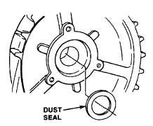
NOTE
Inspect felt dust shield for damage,
replace if necessary. Install in recess
as shown in Figure No. 47.
FIGURE NO. 47.
ROTOR ELECTRICAL TEST AND INSPECTION -
Check rotor assembly for the following (Figure No. 48):
A.
Continuity and current draw of rotor winding.
1.
.55 to 1.5 ampere at 1 0.Ovolts(70°toB°
F).
2.
11.0 to 12.5ohms.
B. Grounded slip ring, ring connecting cables or
rotor winding.
1.
No circuit from either ring to rotor body.
C. Condition of slip rings.
1.
Clean brush contacting surfaces with fine
crocus cloth, wipe dust off.
2.
If surface is damaged beyond restoration,
replace rotor assembly.
3.
Do not machine surface of slip rings.
D. Rear bearing assembly.
1.
If loose or dry, replace bearing.
E. Rotor shaft and body assembly.
1.
Worn key slot.
2.
Worn bearing surface, front area.
3.
Scuff marks on pole fingers.
4.
Stripped threads.
FIGURE NO. 48.
F-292
|