| |
TM 10-3930-671-24
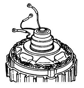
STATOR REMOVAL-
1.
Grasping the stator, apply pressure to separate
stator from housing (Figure No. 37).
FIGURE NO. 37.
All connections of the TA stator are either welded or
crimped and should not be taken apart. Do not attempt
to solder replacement leads to the ends of the windings.
The test procedure for each type stator is different, due
to the fourth test point on the Wye stator. The objective
is the same. The tests must indicate that: (1) all
windings are a complete circuit. (2) They are not short
circuited to each other. (3) The windings are not
grounded. Discoloration of the enamel on the windings
is evidence of overheating and may cause a shorted
condition. Test stator leads as indicated in Figure No’s.
38 & 39.
FIGURE NO. 38.
FIGURE NO. 39.
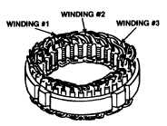
STATOR SERVICE OPERATIONS - The alternator
stator consists of three individual windings wound on a
common core or lamination. The lamination is Insulated
tor durability (Figure No. 40).
FIGURE NO. 40.
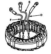
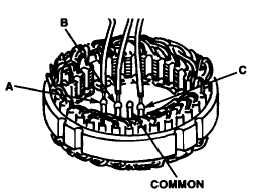
The usual reference to alternator stators concerns the
method of terminating the ends of the three windings.
They may be connected in a Wye, or a Delta circuit
(Figure No’s. 41 and 42). The Delta circuit used in 30
and 45 ampere TA alternators, does not have the
common termination, just three connecting leads for the
rectifying diodes (D - E - F), (Figure No. 41).
F-290
|