| |
TM 10-3930-671-24
The negative, rectifier diodes, are pressed in the rear
housing (Figure No. 32).
FIGURE NO. 32.
CAUTION
Do
not
attempt
to
substitute
a
replacement diode and solder the
lead to the diode stem. The internal
heat of the alternator may rise to the
point, to soften solder.
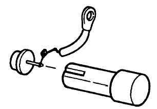
The rectifying diode used in the ’TA" alternator have their
leads welded, not soldered, to the stems (Figure No.
33).
FIGURE NO. 33.
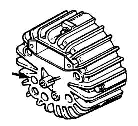
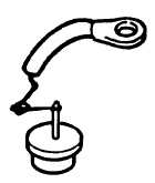
Defective diodes may be pressed out of the heat sink or
the rear housing using regular diode service tools. In
every case, support the underside of the casting involved
to prevent breakage (Figure No’s. 34 & 35).
FIGURE NO. 34.
FIGURE NO. 35.
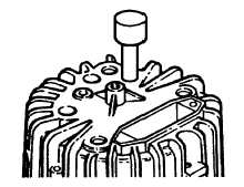
Do not press diodes into same fluted opening of heat
sink, a slight twist will allow new diode to cut its own
opening providing more efficient transfer of heat from the
diode. A typical diode installation tool is shown in (Figure
No. 36).
FIGURE NO. 36.
Replace rear housing or heat sink if either is cracked
while exchanging diodes. Retest diodes after assembly
prior to attaching circuit leads.
F-289
|