| |
TM 10-3930-671-24
3.
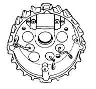
Remove the three black leads from the heat sink
screws and gently push the heat sink out of the
housing. Observe loose leads as plate is being
removed, so as not to damage leads (Figure No.
28).
NOTE
Three mica insulators are set against
the inside of the rear housing and
insulate positive heat sink from rear
housing (Figure No. 28). The mica
insulators are retained by a recess in
the rear housing, plus the use of
silicon grease.
FIGURE NO. 28.
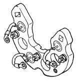
OUT OF CIRCUIT RECTIFIER DIODE TEST - If a
commercial alternator rectifier diode tester is available,
follow manufacturer’s instructions to test all diodes. Do
Not Use 120 Volt AC test lamp.
A 12 Volt battery operated test lamp may be used if a
commercial tester is not available. Connect one test
lead to diode heat sink, the other to each diode wire
terminal, Figure No. 29, then repeat test with test leads
reversed. Lamp should light with leads in one position,
but should not light with test leads reversed. All diodes
in heat sink (Figure No. 29) or rear housing (Figure No.
30) should show the same results.
FIGURE NO. 29.
FIGURE NO. 30.
If lamp lights, regardless of how test leads are switched,
the diode is shorted. If lamp fails to light in either test,
the diode is open. Replace defective diodes, observe
correct polarity by color of stamping used to list part
number on diode.
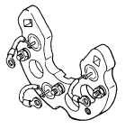
REPLACING DEFECTIVE RECTIFIER DIODES-
Note, head of output stud, is a metal to metal contact.
Figure No. 31 shows three positive, rectifier diodes, and
terminal studs assemblied in the positive heat sink.
FIGURE NO. 31.
F-288
|