| |
TM 10-3930-671-24
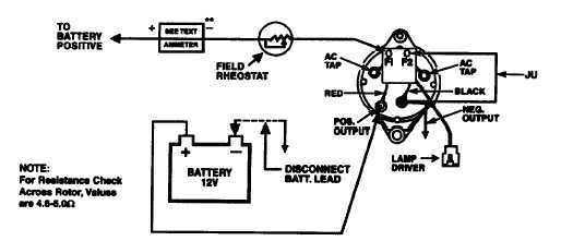
FIELD CIRCUIT TEST (45 Amp Systems)- With the engine not running, remove the regulator from the alternator and
disconnect leads F1 and F2 from field terminals Fl and F2. Connect field rheostat and jumper (JU) to the appropriate
terminals as shown in in the applicable ground system (Figure No. 11.1). Disconnect grounded battery cable and place
test ammeter switch to a current range of approximately 0 to 10 amperes. Set control knob of field rheostat to maximum
resistance position and connect as shown in Figure No. 11.1. The rheostat will protect the ammeter from damage if the
field circuit is shorted.
Reconnect battery ground cable and slowly reduce rheostat resistance and note the rise in the ammeter reading. Stop test
if meter indicates more than 5.0 amperes. Altemator disassembly may be necessary to correct condition.
If entire rheostat resistance can be eliminated with test ammeter below 5.0 amperes, the indicated current is the field
current draw. If the test ammeter fluctuates when the rotor is moved slightly, the brushes and slip rings require cleaning.
FIGURE NO. 11.1
F-280
|