| |
TM 10-3930-671-24
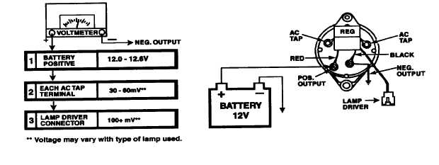
LAMP CIRCUIT TEST (45 Amp Systems)- With ignition
switch on, lamp on, and engine not running, connect a
DC voltmeter to Test Point I as shown in Figure 9.1. A
plus 12.0-12.6 volts measurement should be noted on
the DC voltmeter. If you receive a low voltage
measurement at Test Point 1, check battery and terminal
connections.
Connect positive voltmeter lead on one of the AC
Tap terminals Test Point 2). The DC voltmeter should
show 30-60 mV. Repeat this procedure on the other AC
Tap terminal. If you receive zero voltage at either AC
Tap terminal, replace regulator.
Connect positive DC voltmeter lead on Lamp Driver lead
(Test Point 3). A measurement of 100+ mV should be
noted. If you obtain a measurement of 100+mV, replace
lamp.
FIGURE NO. 9.1
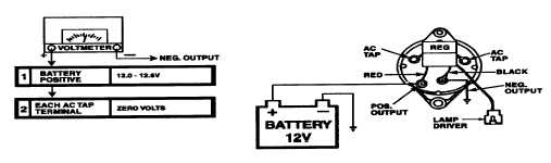
SHORTED
RECTIFIER
DIODE
TEST(45
Amp
Systems)- With ignition switch off and engine not
running, connect a DC voltmeter to Test Point 1 as
shown
in
Figure
9.2.
A
plus
12.0-12.6
volts
measurement should be noted on the DC voltmeter. If
you receive a low voltage measurement at Test Point 1,
check battery and terminal connections.
Connect positive voltmeter lead on one of the AC
Tap terminals (Test Point 2). The DC voltmeter should
not show any voltage. Repeat this procedure on the
other AC Tap terminal. Any voltage at either AC Tap
terminal indicates a shorted positive rectifier diode in the
alternator. Repair alternator.
FIGURE NO. 9.2
F-277
|