| |
TM 10-3930-671-24
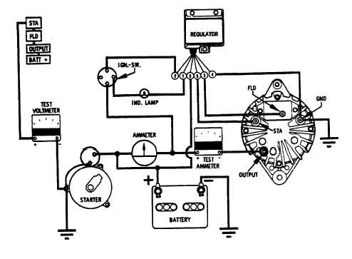
REED SWITCH AND POSITIVE RECTIFIER DIODE
TEST (22/30 Amp Systems)- With ignition switch off,
engine not running, temporarily disconnect battery
ground cable from battery. Connect test AMMETER,
using 0-50 ampere scale, between alternator output
terminal and original output lead. Secure leads and
reconnect battery (Figure No. 9).
Connect test VOLTMETER as follows: negative lead to
negative battery terminal, positive lead to points STA.,
FLD. and OUTPUT, in that order. With voltmeter,
connect to STA. then FLD. in both tests, meters should
read "Zero". Move positive lead to OUTPUT terminal,
meter should read battery voltage 12.0 to 12.6 volts.
Ammeter should read "Zero" amperes.
If voltmeter at test point STA. indicates above "Zero"
volts, one of the positive rectifying diodes is shorted.
Test ammeter will indicate current discharge. Remove
alternator from engine and make necessary repairs.
If voltmeter at test point FLD., indicates above zero volts,
there is a fault in the regulator allowing the reed switch to
remain closed. The test ammeter will indicate current
discharge and the charge indicator lamp may glow.
Replace regulator and retest.
FIGURE NO. 9.
F-276
|