| |
TM 10-3930-671-24
CIRCUIT DESCRIPTION
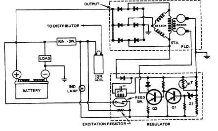
ALTERNATOR - The alternator produces power in the
form of three phase alternating current and voltage. The
alternating current is rectified to direct current by a three
phase full wave rectifier circuit, using six silicon rectifier
diodes. Since the diodes will pass current in only one
direction (from altemator to battery), the altemator does
not require the use of a cut out relay (Figures No. 5 and
No. 5.1). The alternator output current is controlled by
the current flow through the field coil, (rotor). The
amount of current required is determined and controlled
by the regulator. Since there is very little residual
magnetism in the alternator, it is necessary to supply a
small amount of excitation current to the field (rotor) to
start the process of current generation. The excitation
resistor (Intemal to the regulator), supplies this starting
current when the ignition is turned on. Once the
alternator is excited, a voltage is developed at the
regulator input terminal and the voltage regulator takes
over control of the system voltage.
REGULATOR (22/30 Amp Systems)- The voltage
regulator is a standard Prestolite regulator. A coil
operated reed switch is enclosed in the regulator housing
and serves to sense regulator input voltage at a specific
point, usually at the starter or battery positive (+)
terminal. The altemator output from the
stator terminal of the alternator energizes the reed switch
coil. When the alternator is not charging, the reed switch
is open. The regulator and alternator field (rotor) are
disconnected from the battery (Figure No.’s 5 and 5.1).
Turning the ignition (control) switch "on", allows initial
field (rotor) activating energy to flow from the battery
positive (+), through the ignition switch, to the excitation
resistor and charge indicator lamp, through the input
circuit of the regulator to the field (rotor) winding. The
reed switch is by-passed at this time and the charge
indicator lamp will glow.
As the alternator develops a charge, part of the AC
component is sensed at the stator (STA) terminal of the
alternator and is conducted through a diode (coil
rectifier), in the regulator, to the reed switch coil to
ground. The magnetized coil turns the reed switch "on",
connecting the regulator input directly to the battery
positive (+) terminal. The charge indicator lamp will be
turned off due to equal voltage at both lamp terminals.
This direct sensing technique provides a true battery
voltage to the regulator and is not subject to improper
readings, due to circuit loss.
REGULATOR (45 Amp
Systems)-
The
regulator
basically acts as a multifunction circuit to operate. It is a
three part circuit: 1) Turn on (self-excited AC turn on, 2)
Regulation, and 3) Lamp Driver Circuit.
ALTERNATOR
22 / 30 Amp Systems with regulator
FIGURE NO. 5
F-272
|