| |
TM 10-3930-671-24
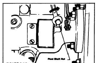
Assemble pivot shaft seals and nuts to the shaft and
tighten both nuts successively to specified torque (Figure
5.11b).
FIGURE 5.11b.
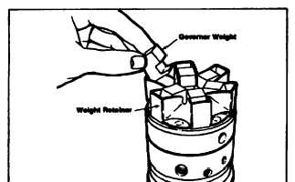
STEP 12 Install the governor weights into the governor
weight retainer as shown in Figure 5.12a.
FIGURE 5.12a.
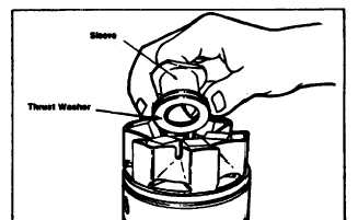
Insert the governor thrust washer and thrust sleeve into
the lower slots of the governor weights by tilting the
weights outward slightly. The two deep grooves of the
thrust sleeve should face upward as installed (Figure
5.12b). Sight across the tops to the assembled weights.
They should all be level and collapsed against the thrust
sleeve.
FIGURE 5.12b.
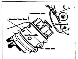
STEP 13 The hydraulic head and rotor assembly,
including the transfer pump assembly, cam ring and
governor assembly, are now ready to be put into the
housing. Install a new seal on the hydraulic head after
first greasing it slightly. Apply a light film of clean grease
around the inside edge of the housing and tilt the
housing slightly downward at the rear to aid in assembly.
Rotate the cam ring so that the unthreaded hole is in line
with the metering valve bore. This will ensure proper
position of the cam ring. Grasp the hydraulic head firmly
in both hands and insert it into the housing bore with a
slight rotary motion (Figures 5.13a and 5.13b). Do not
force. If the assembly should jam during insertion,
withdraw and start over.
Exercise care not to insert the head assembly too far into
the housing. Pushing the head in too far will damage the
seal on the hydraulic head and result in leakage.
FIGURE 5.13a.
F-240
|