| |
TM 10-3930-671-24
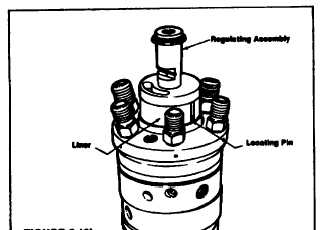
FIGURE 5.10a.
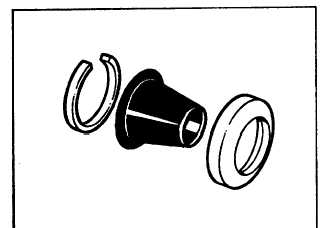
Assemble the filter screen to the pressure plate and
install the screen retaining ring (Figure 5.10c).
FIGURE 5.10c.
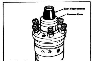
Install the assembled pressure plate and screen onto the
transfer pump regulator assembly (Figure 5.10Od).
Coat the beveled surface of the pressure plate and the
threads on the outside diameter of the end cap with
clean grease.
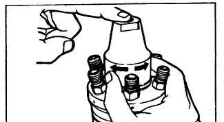
Install the transfer pump end cap and thread into the
hydraulic head by applying a slight pressure on top of the
end cap. Rotate the cap counterclockwise until a slight
“click" is heard, now turn the cap clockwise by hand until
tight (Figure 5.10e).
FIGURE 5.10e.
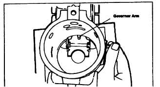
STEP 11 Place the governor arm in position in the
housing (Figure 5.11a).
NOTE
Insert the pivot shaft, with the knife edge mating with
the groove in the governor arm.
FIGURE 5.11a.
FIGURE 5.10d.
F-239
|