| |
TM 10-3930-671-24
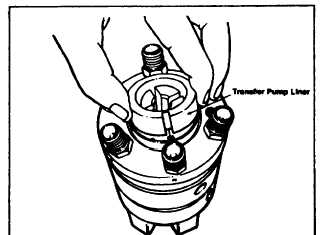
STEP 9 Insert the transfer pump liner so that the slot is
in line with the hole which the regulator assembly rollpin
enters (Figure 5.9a).
FIGURE 5.9a.
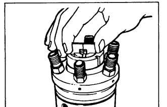
Assemble springs to transfer pump blade halves and
install the blades in their slots in the rotor (Figure 5.9b).
The blade springs must be fully compressed as they are
installed and care should be taken not to cock the blades
during installation, as the sharp edge of the liner can
score the blade ends.
NOTE
A number of rotors have oversized blade slots (.001
in. [.0254mm] wider than normal). Oversized blade
should always be tried first when assembling a
pump. If oversized blades fit any of the slots, they
should be used in those slots. It is permissible to
use both oversize and standard size blades in the
same rotor.
FIGURE 5.9b.
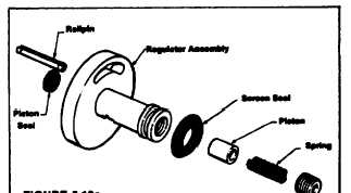
STEP 10 Assemble the transfer pump regulator
components (Figure 5.10a). Install the inlet filter screen
seal on the regulator. Using regulating sleeve adapter,
place
the regulating piston seal in the groove of the regulator.
Do not roll the seal over when assembling.
NOTE
Some DB2 models no longer use this seal, but
instead have a bushing pressed into the regulator in
its place. This bushing should not be removed and,
when present, no seal is required.
Install the piston to the regulator with the hollow end
facing the spring or the threaded end of the bore. Install
the regulating spring and adjusting plug. This plug
contains the viscosity compensating orifice and should
be installed so that the top of the screw is flush with the
end of the regulator assembly. Using regulating sleeve
adapter, check the regulating piston for freedom of
movement in its bore.
Turn the adjusting plug in until it is flush with end of
regulator so damage to the pump will not result from
excessive transfer pump pressure when the pump is
operated.
FIGURE 5.10a.
Assemble the regulator to the liner (Figure 5.10b).
Check that the liner locating pin is in the correct hole in
the regulator for proper pump rotation. On the face of the
regulator "C" or "CC" is stamped for clockwise or
counterclockwise pump rotation.
F-238
|