| |
TM 10-3930-671-24
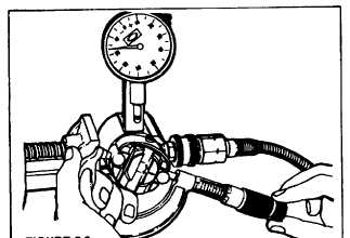
STEP 3 Install roller to roller dimension setting fixture in
a vise (clamping on the flat) so that the air inlet hole is
not covered by the vise. Assemble a 1.4" 18 N.PT. fitting
to the air inlet of the fixture. This fitting should be
adapted to a supply of clean, filtered, compressed air,
regulated to a pressure between 40 and 100 p.s.i.
Handle the rotor carefully, holding the rollers and shoes
in their slots. Install the rotor assembly to the fixture on
the air inlet side. Using a micrometer, measure the roller-
to-roller dimension (Figure 5.3) (distance between the
outer surfaces of the opposed cam rollers) and compare
this with the specification. To set the roller-to roller
dimension to the pump specification, turn the leaf spring
adjusting screw inward (clockwise) to increase and
outward (counterclockwise) to reduce the roller to-roller
dimension.
NOTE
The roller-to-roller setting provides a completely
accurate maximum fuel adjustment and it should not
differ
from
that
shown
in
the
applicable
specification.
FIGURE 5.3.
A centrality check is now required. Refer to specifications
page for allowable tolerances and check as follows:
a. After setting the roller-to-roller dimension to the
amount indicated on the specification, rotate the rotor
until one roller is aligned with the dial indicator plunger.
Slide the indicator inward until the plunger depresses it at
least .010" (.25mm). Lock the indicator retaining screw.
’Zero" the indicator on high point of roller by rotating
knurled dial.
b. Rotate rotor (either direction) until the other roller
depresses the dial indicator plunger.
c. If roller centrality is beyond specified tolerance (see
injection pump specification), roller and/or shoes can be
interchanged. Recheck centrality after each change and
be sure to recheck the roller-to-roller dimension.
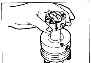
STEP 4 Rinse the hydraulic head assembly in clean
calibrating oil. Remove the rotor assembly from the
fixture, taking care that the shoes and rollers do not
leave their respective slots and rinse in oil. Carefully,
insert the rotor assembly into the hydraulic head (Figure
5.4).
FIGURE 5.4.
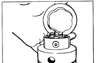
STEP 5 Place the cam ring onto the head and rotor
assembly with directional arrow indicating the direction of
rotation of the pump (Figure 5.5) (Pump rotation is
expressed as viewed from the drive end.). If the cam ring
is installed incorrectly, the pump will not be in time with
the engine.
FIGURE 5.5.
STEP 6 Place the weight retainer assembly on the rotor
(Figure 5.6a).
Make sure the assembly marks on the rotor and the
retainer line up with each other. Assemble the snap ring
to its groove (Figure 5.6b).
F-236
|