| |
TM 10-3930-671-24
SECTION 5 REASSEMBLY
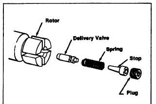
STEP 1 Rinse rotor thoroughly in clean fuel or calibrating
oil. Place the rotor on rotor support and secure rotor
support in vise. Install the delivery valve to its bore using
extractor. Make sure it slides freely in its bore.
NOTE
Do not mistake slight interference of the retractor
collet in the bore for delivery valve sticking. If the
valve is not secured straight and tight in the
retractor collet, the collet diameter can drag in the
rotor bore.
Install delivery valve spring and a new delivery valve stop
to the rotor bore (Figure 5.1). Installation of a used stop
can result in leakage and low output at cranking speeds.
Start the delivery valve retaining screw into the bore
using the hex end of the delivery valve Extractor. Tighten
the screw to the specified torque.
Excessive tightening of this screw may cause
seizure of the hydraulic head and rotor assembly.
Insufficient torque may cause leaking and hard
starting.
FIGURE 5.1.
DELIVERY VALVE REPLACEMENT
Delivery valves of various retraction values are used for
different applications. Correct part numbers are found on
individual pump specifications. The letters ’OV" etched
on the base of the rotor indicate a .001’ oversize delivery
valve bore. A rotor so marked must use a .001" oversize
delivery valve. Part numbers for both standard and
oversize
valves
are
listed
on
individual
pump
specifications. The oversize valve is also identified by
blackening
on
both
ends
and
in
the
groove
on the delivery valve shank.
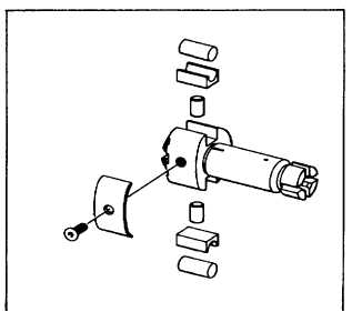
STEP 2 Remove the rotor from the holding fixture and
submerge it in clean calibrating oil. Install the pumping
plungers and check them for freedom of movement.
Assemble the leaf spring, leaf spring adjusting screw and
shim (if used) to the rotor (Figure 5.2).
FIGURE 5.2.
PLUNGER REPLACEMENT
Since the plungers are positioned centrally in the bore
during operation and their travel is extremely short, wear
of plungers is negligible. Replacement, however, may be
made in instances where rust or damage in handling has
occurred. Plungers of any given nominal diameter are
graded in four select fit sizes: A, B, C, and D. The rotor is
etched with the letter indicating bore size. This mark is
found on the base of the rotor. If plunger replacement is
required, check the size designation on the rotor and use
the plunger of corresponding part number as indicated
on individual specifications. For example: A .330"
diameter plunger bears basic part No. 11076 and the
graded sizes, A through D, bear part No. 11077 through
11080, respectively. The replacement plungers for a
.330’ diameter plunger pump with a rotor marked C"
would be part No. 11079. Always refer to correct
individual specifications for part numbers.
NOTE
A limited number of pumps will have a “-2” etched
on the rotor following the letter grading code. This
mark indicates a .002" (.05rm) oversize plunger bore.
Replacement should be ordered according to the
oversize plunger group shown on individual
specifications.
F-235
|