| |
TM 10-3930-671-24
due to the cam rollers passing the highest point on the
cam lobe.
Following this, the rotor discharge port closes completely
and a residual injection line pressure is maintained. Note
that the delivery valve is only required to seal while the
discharge port is opened. Once the port is closed,
residual line pressures are maintained by the seal of the
close fitting head and rotor.
G.
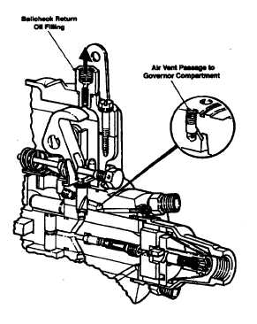
RETURN OIL CIRCUIT
Fuel under transfer pump pressure is discharged into a
vent passage in the hydraulic head (Figure 1.10). Flow
through the passage is restricted by a vent wire
assembly to prevent excessive return oil and undue
pressure loss. The amount of return oil is controlled by
the size of wire used in the vent wire assembly, i.e. the
smaller the wire the greater the flow and vice versa. The
vent wire assembly is available in several sizes in order
to meet the return oil quantities called for on the
specification. Note that this assembly is accessible by
removing only the governor cover. The vent passage is
located behind the metering valve bore and connects
with a short vertical passage containing the vent wire
assembly and leads to the governor compartment.
Should a small quantity of air enter the transfer pump, it
immediately passes to the vent passage as shown. Air
and a small quantity of fuel then flow from the housing to
the fuel tank and via the return line.
Housing pressure is maintained by a spring-loaded
ballcheck return fitting in the governor cover of the pump.
H.
MECHANICAL ALL SPEED GOVERNOR
The governor serves the purpose of maintaining the
desired engine speed within the operating range under
various load settings.
In the mechanical governor (Figure 1.11), the movement
of the weights acting against the governor thrust sleeve
rotates the metering valve by means of the governor arm
and linkage hook. This rotation varies the registry of the
metering valve opening to the passage from the transfer
pump, thereby controlling the quantity of fuel to the
plungers. The governor derives its energy from weights
pivoting in the weight retainer. Centrifugal force tips
them outward, moving the governor thrust sleeve against
the governor arm, which pivots on the knife edge of the
pivot shaft and, through a simple, positive linkage,
rotates the metering valve. The force of the weights
against the governor arm is balanced by the governor
spring force, which is controlled by the manually
positioned throttle lever and vehicle linkage for the
desired engine speed.
In the event of a speed increase due to a load reduction,
the resultant increase in centrifugal force of the weights
rotates the metering valve clockwise to reduce fuel. This
limits the speed increase (within the operating range) to
a value determined by governor spring rate and setting of
the throttle.
When the load on the engine is increased, the speed
tends to reduce. The lower speed reduces the force
generated by the weights permitting the spring force to
rotate the metering valve in the counterclockwise
direction to increase fuel. The speed of the engine at any
point within the operating range is dependent upon the
combination of load on the engine and the governor
spring rate and setting as established by the throttle
position. A light idle spring is provided for more sensitive
regulation when weight energy is low in the low end of
speed range. The limits of throttle travel are set by
adjusting screws for proper low idle and high idle
positions.
A light tension spring on the linkage assembly takes up
any slack in the linkage joints and also allows the shutoff
mechanism to close the metering valve without having to
overcome the governor springing force. Only a very light
force is required to rotate the metering valve to the
closed position.
FIGURE 1.10.
F-220
|