| |
TM 10-3930-671-24
The plungers move outward a distance proportionate to
the amount of fuel required for injection on the following
stroke. If only a small quantity of fuel is admitted into the
pumping chamber, as at idling, the plungers move out a
short
distance.
Maximum
plunger
travel
and,
consequently, maximum fuel delivery are limited by the
leaf spring which contacts the edge of the roller shoes.
Only when the engine is operating at full load will the
plungers move to the most outward position. Note that
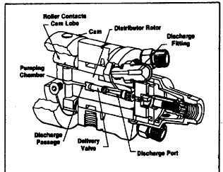
while the angled inlet passages in the rotor are in registry
with the ports in the circular charging passage, the rotor
discharge port is not in registry with a head outlet (Figure
1.7). Note also that the rollers are off the cam lobes.
Compare their relative positions (Figures 1.7 and 1.8).
Discharge Cycle
As the rotor continues to revolve (Figure 1.8), the inlet
passages move out of registry with the charging ports.
The rotor discharge port opens to one of the head
outlets. The rollers then contact the cam lobes forcing
the shoes in against the plungers and high-pressure
pumping begins.
Beginning of injection varies according to load (volume of
charging fuel), even though rollers may always strike the
cam at the same position. Further rotation of the rotor
moves the rollers up the cam lobe ramps pushing the
plungers inward. During the discharge stroke, the fuel
trapped between the plungers flows through the axial
passage of the rotor and discharge port to the injection
line. Delivery to the injection line continues until the
rollers pass the innermost point on the cam lobe and
begin to move outward. The pressure in the axial
passage is then reduced, allowing the nozzle to close.
This is the end of delivery.
F.
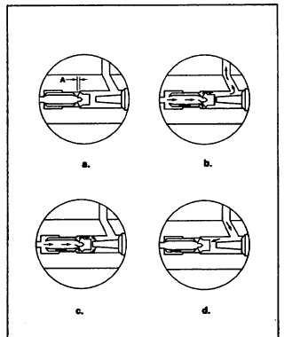
DELIVERY VALVE
The delivery valve (Figures 1.9a through 1.9d) rapidly
decreases injection line pressure after injection to a
predetermined value lower than that of the nozzle closing
pressure. This reduction in pressure permits the nozzle
valve to return rapidly to its seat, achieving sharp delivery
cutoff and preventing improperly atomized fuel from
entering the combustion chamber.
FIGURE 1.9.
The delivery valve operates in a bore in the center of the
distributor rotor. Note that the valve requires no seat only
a stop to limit travel. Sealing is accomplished by the
close clearance between the valve and bore into which it
fits. Since the same delivery valve performs the function
of retraction for each injection line, the result is a smooth
running engine at all loads and speeds.
When injection starts, fuel pressure moves the delivery
valve slightly out of its bore and adds the volume of its
displacement, section "A," to the delivery valve spring
chamber. Since the discharge port is already opened to a
head
outlet,
the
retraction
volume
and
plunger
displacement volume are delivered under high pressure
to the nozzle. Delivery ends when the pressure on the
plunger side of the delivery valve is quickly reduced.
FIGURE 1.8.
F-219
|