| |
TM 10-3930-671-24
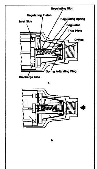
pressure on the piston is opposed by the regulating
spring, the delivery pressure of the transfer pump if
controlled by the spring rate and size of the regulating
slot "A." Therefore, pressure increases with speed.
A high-pressure relief slot ’B" is incorporated in some
regulators as part of the pressure regulating slot to pre
vent excessively high transfer pump pressure, if the
engine or pump is accidentally overspeeded.
FIGURE 1.6.
VISCOSITY COMPENSATION
The DB2 transfer pump works equally well with different
grades of diesel fuel and varying temperatures, both of
which affect fuel viscosity. A unique and simple
feature of the regulating system offsets pressure
changes caused by viscosity difference. Located in the
spring adjusting plug is a thin plate incorporating a
sharpedged orifice. The orifice allows fuel leakage past
the piston to return to the inlet side of the pump. Flow
through a short orifice is virtually unaffected by viscosity
changes. The biasing pressure exerted against the back
side of the piston is determined by the leakage through
the clearance between the piston and the regulator bore
and the pressure drop through the sharpedged orifice.
With cold or viscous fuels, very little leakage occurs past
the piston. The additional force on the back side of the
piston from the viscous fuel pressure is slight. With hot
or light fuels, leakage past the piston increases. Fuel
pressure In the spring cavity increases also, since flow
past the piston must equal flow through the orifice.
Pressure rises due to increased piston leakage and
pressure rises to force more fuel through the orifice. This
variation in piston position compensates for the leakage
which would occur with thin fuels and design pressures
are maintained over a broad range of viscosity changes.
E.
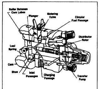
CHARGING AND DISCHARGING
Charging Cycle
As the rotor revolves (Figure 1.7), the two inlet passages
in the rotor register with ports of the circular charging
passage. Fuel under pressure from the transfer pump,
controlled by the opening of the metering valve, flows
into the pumping chamber forcing the plungers apart.
FIGURE 1.7.
F-218
|