| |
TM 10-3930-671-24
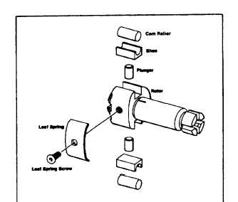
FIGURE 1.4.
D.
TRANSFER PUMP
The positive-displacement, vane-type fuel transfer pump
consists of a stationary liner and spring-loaded blades
which are carried in slots in the rotor. Since the inside
diameter of the liner is eccentric to the rotor axis, rotation
causes the blades to move in the rotor slots.
This blade movement changes the volume between the
blade segments.
Transfer pump output volume and pressure increases as
pump
speed
increases.
Since
displacement
and
pressure of the transfer pump can exceed injection
requirements, some of the fuel is recirculated by means
of the transfer pump regulator to the inlet side of the
transfer pump.
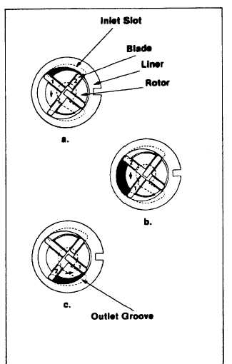
Figure 1.5 illustrates the pumping principle. Radial
movement causes a volume increase in the quadrant
between blades 1 and 2 (Figure 1.5a). In this position,
the quadrant is in registry with a kidney-shaped inlet slot
in the top portion of the regulator assembly. The
increasing volume causes fuel to be pulled through the
inlet fitting and filter screen into the transfer pump liner.
Volume between the two blades continues to increase
until blade 2 passes out of registry with the regulator slot.
At this point, the rotor has reached a position where
outward movement of blades 1 and 2 is negligible and
volume is not changing (Figure 1.5b). The fuel between
the blades is being carried to the bottom of the transfer
pump liner.
As blade 1 passes the edge of the kidney-shaped groove
in
the
lower
portion
of
the
regulator
assembly
(Figure 1.5c), the liner, whose inside diameter is
eccentric to the rotor, compresses blades 1 and 2 in an
inward direction (Figure 1.5a). The volume between the
blades is reduced and pressurized fuel is delivered
through the groove of the regulator assembly, through
the transfer pump, through the rotor, past the rotor
retainers and into a channel on the rotor leading to the
hydraulic head passages. Volume between blades
continues to decrease, pressurizing the fuel in the
quadrant, until blade 2 passes the groove in the regulator
assembly.
FIGURE 1.5.
REGULATOR ASSEMBLY OPERATION
Figure
1.6
shows
the
operation
of
the
pressure
regulating piston while the pump is running. Fuel output
from the discharge side of the transfer pump forces the
piston in the regulator against the regulating spring. As
flow increases, the regulating spring is compressed until
the edge of the regulating piston starts to uncover the
pressure regulating slot "S" (Figure 1.6b). Since fuel
F-217
|