| |
TM 10-3930-671-24
The DB2 pump contains its own mechanical governor
capable of close speed regulation. The centrifugal force
of the weights in their retainer is transmitted through a
sleeve to the governor arm and through a positive
linkage to the metering valve. The metering valve can
be closed to shut off fuel through a solid linkage by an
independently operated shutoff lever, or by an electrical
solenoid.
The automatic advance is a hydraulic mechanism which
advances or retards the pumping cycle.
B.
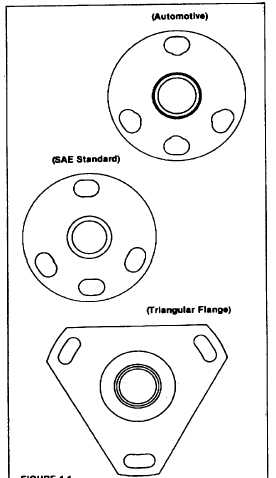
MOUNTING FLANGES
FIGURE 1.1
Shown above are the typical DB2 mounting flange
configurations. These are the three most common
types. Note that the automotive flange has scalloped
slots to enable it to be mounted on a standard pump
holding fixture.
C.
FUEL FLOW
The operating principles of the pump can be understood
more readily by following the fuel circuit during a
complete pump cycle cutaway, (Figure 1.2) and fuel flow
schematic (Figure 1.3). Also, see exploded view of the
rotor assembly (Figure 1.4).
Fuel is drawn from the supply tank through filters into the
pump inlet through the inlet filter screen (1) by the vane-
type fuel transfer pump (2). Some fuel is bypassed
through the pressure regulator assembly (3) to the
suction side.
Fuel under transfer pump pressure flows through the
center of the transfer pump rotor, past the rotor retainers
(4) into a circular groove on the rotor. It then flows
through a connecting passage (5) in the head to the
automatic advance (6), up through a radial passage (7)
and then through a connecting passage (8) to the
metering valve. The radial position of the metering
valve, controlled by the governor, regulates flow of the
fuel into the radial
charging
passage
(9)
which
incorporates the head charging ports.
As the rotor revolves, the two rotor inlet passages (10)
register with the charging ports in the hydraulic head,
allowing fuel to flow into the pumping chamber. With
further rotation, the inlet passages move out of registry
and the discharge port of the rotor registers with one of
the head outlets. While the discharge port is opened, the
rollers (11) contact the cam lobes forcing the plungers
together. Fuel trapped between the plungers is then
pressurized
and
delivered
by
the
nozzle
to
the
combustion chamber.
Self-lubrication of the pump is an inherent feature of the
Roosa Master design. As fuel at transfer pump pressure
reaches the charging ports, slots on the rotor shank
allow fuel and any entrapped air to flow into the pump
housing cavity.
In addition, an air vent passage (12) in the hydraulic
head connects the outlet side of the transfer pump with
the pump housing. This allows air and some fuel to be
bled back to the fuel tank via the return line. The fuel
thus bypassed fills the housing, lubricates the internal
components, cools and carries off any small air bubbles.
The pump operates with the housing completely full of
fuel; there are no dead air spaces anywhere within the
pump.
F-215
|