| |
TM 10-3930-671-24
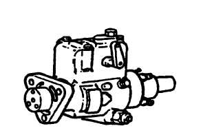
Injection Pump
WARNING
Before disconnecting lines, be sure to relieve all
pressure. Before applying pressure to the system, be
sure all connections are tight and that lines, pipes, and
hoses are not damaged. Use a piece of cardboard,
rather than hands, to search for leaks. Escaping fluid
under pressure can have sufficient force to penetrate the
skin, causing personal injury. If injured by escaping fluid,
get medical attention at once.
The fuel injection pump, flange mounted to the engine, is
a
compact,
self-contained,
distributor-type
unit
incorporating a sensitive all-speed governor. It has a
relatively simple design that utilizes no ball or roller
bearings, gears, or highly-stressed springs. The number
of working parts remains the same regardless of the
number of cylinders the pump is required to serve.
It is constructed to be oil tight. During operation, all
moving parts are lubricated and cooled by fuel under
pressure. No additional lubrication system is required.
Pressure maintained within the pump housing prevents
the ingress of dust, water, or other foreign matter.
Fuel injection is effected by a single element having twin
opposed plungers located within a transverse bore in a
central rotating member. This acts as a distributor and
revolves in a stationary member known as the hydraulic
head. The pump plungers are actuated by lobes on an
internal cam ring. Fuel is accurately metered to the
pumping element, and the high-pressure charges are
distributed to the engine cylinders at the required timing
intervals through ports in the rotor and the hydraulic
head.
The internal cam ring, mounted in the pump housing,
operates the opposed pump plungers through cam
rollers carried in shoes sliding in the rotor body. The
plungers are forced inwards simultaneously as the rollers
contact the diametrically-opposed cam lobes. This is the
injection stroke. The plungers are returned by pressure
of the in flowing fuel during the charging stroke. The
pump rotor is driven by the engine through pinned hub
and gear.
Most pumps have an automatic device which varies the
point of commencement of injection.
The single pumping element ensures uniform delivery of
fuel to each cylinder, and eliminates having to balance
the deliveries from each of the high-pressure delivery
lines.
The integral governor is a mechanical flyweight type
which gives accurate control of engine speed under all
load conditions. The governor flyweight assembly is
mounted on the drive shaft and is contained entirely
within the pump body. Linkage transmits the movement
of the governor flyweights to the control lever on the
metering valve. The governor control mechanism is
enclosed in a housing mounted on the pump body.
Injection Pump Overhaul
Dismantling, assembly, testing, and adjustment of the
injection pump must be carried out by trained personnel,
using specialized tools and test apparatus.
Timing Of Injection Pump
To The Engine
Injection pumps must be installed on the engine in
accurate alignment and timed to correct relation with the
engine crankshaft for proper engine operation with
maximum
power
and
economy
and
to
prevent
complaints of hard starting, overheating, uneven running,
and excessive smoking.
Timing a fuel injection pump to a diesel engine is similar
to, and simpler than, timing a gasoline engine ignition
system. Both require precision to ensure the correct
timing as recommended by the engine manufacturer.
F-206
|