| |
TM 10-3930-671-24
When the correct fit is obtained you must be able to
withdraw the feeler with a pull of 5-10 pounds (2.3-4.5
kg) on the scale, with the feeler inserted between the
piston and the cylinder mid-way between the piston pin
bosses where the diameter of the piston is the greatest.
Check the fit of the piston when it is approximately 2"
(50mm) down to the cylinder bore in an inverted position.
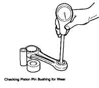
PISTON PINS
Check the bushing in the upper end of the connecting
rod for wear. If worn and you are using the original
pistons, an oversize piston pin may be obtained in .003
or .005" (0.08 or 0.13mm) oversize.
The piston pin hole in the piston and the bushing in the
connecting rod may be honed to increase their diameter
to obtain the desired fit as shown in our Limits and
Clearance Chart.
Note that, while the chart specifies a light press of the pin
in the piston, there is a definite clearance of the piston
pin in the connecting rod.
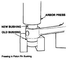
CONNECTING RODS
Replace the bushing in the connecting rod if new pistons
are used. Using the arbor press, press out the old
bushing and press in the new one making sure the oil
supply holes line up-after which the bushing must be
honed to obtain the correct fit of the pin in the bushing as
shown on Limits and Clearance Chart. If there is an
excess of stock in the piston pin bushing, it may be
reamed first, then honed. In any event, the final
operation should be done with a hone to obtain the
desired fit with better than 75% bearing area contact on
the pin.
PISTON & CONNECTING ROD ASSEMBLY
1.
Assemble the pistons on the connecting rod.
Heating
them
in
hot
water
will
facilitate
assembly. When heated, the piston pin will
enter the piston very easily and can be tapped
through the connecting rod and into place
without distorting the piston. The snap rings
must be assembled in the grooves, making sure
they are fully seated in place.
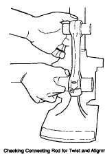
2.
The piston pin hole in the connecting rod must
be parallel to and in plane with, the large bore in
the bearing end of the connecting rod.
F-176
|