| |
TM 10-3930-671-24
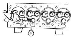
Cleaning Combustion Pocket
Clean and insert combustion pocket. Inspect carefully
for cracks.
4.
Remove all carbon from combustion areas using
scraper and wire brush.
5.
Clean the cylinder head thoroughly with a solvent
or degreasing solution and blow it off with air
pressure. Inspect carefully for cracks.
VALVE GUIDES
1.
Clean the valve stem guides, removing lacquer
or other deposits. Do not use tools that remove
metal.
2.
Check guides for wear by using a telescope
gauge and 1" micrometer. Replace all guides
that are worn bell-mouthed or have increased
.0015" (0.038mm) in diameter. See Limits and
Clearance
Section
for
maximum
diameter
permissible to determine actual amount it has
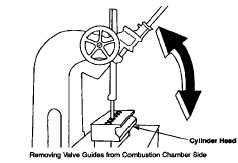
increased. Remove all valve guides when
necessary by pressing them out from the
combustion chamber side.
3.
Replace worn guides as required by pressing in
new guides to the correct depth as given in the
Valve Guide Data figure on the following page.
CAUTION
When replacing guides do not ream
since these are all pre-reamed before
being
ferrox
coated-any
further
reaming will remove the coating and
damage guides.
VALVE SEAT INSERTS (IF SUPPLIED)
1.
The exhaust valve seat insert is held in place by
a shrink fit.
Inspect all exhaust valve inserts in the head and
replace any that are loose, cracked or other wise
damaged. Use puller for removing faulty insert.
2.
When required to replace with new insert, clean
and counterbore for .010" (0.25mm) larger insert
using counterbore tool with correct fitting pilot.
When machining the counterbore, be sure to go
deep enough with the tool to clean up the bottom
so that the insert will have full contact to carry
away the heat.
Continental does not recommend installing new
inserts having the same outside diameter as the
one removed.
New insert installation must have a press fit.
Chill insert in container with dry ice for 20
minutes before assembling.
Insert may then be installed in the counterbore
using a piloted driver and arbor press, without
the possibility of shearing the side walls. This
assures it being seated firmly on the bottom of
the counterbore.
3.
Grind the intake and exhaust valve seats in the
head in accordance with instructions in the Valve
Guide Data figure. Before removing the arbor,
indicate the seat. Total indicator reading of the
runout must not be more than .002" (0.05mm) .
Use a pilot having a solid stem with a long taper,
as all valve seats must be ground concentric and
square with either new or worn valve stem guide
holes.
F-169
|