| |
TM 10-3930-671-24
11.
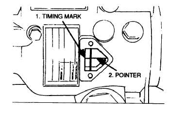
Turn the injection pump gear until the internal
timing marks are lined up (See Below).
Turn the injection pump gear until timing mark is aligned
with the pointer
12.
Guide the injection pump into position and install
the three long
M10
mounting
bolts,
lock
washers, and nuts that secure the adaptor
mounting plate to the engine. Torque the M10
bolts to 25-30 lb-ft (34-40 N•m).
13.
Inspect the internal timing marks again. The two
marks should look like one unbroken horizontal
line. If not, you must judge as to whether the
pump gear is one tooth or more out of time or if
a minor rotation of the injection pump body will
align the marks. If the marks are far apart,
repeat step 12 because the pump gear is
probably out of time. If the marks are very close
together, rotate the body of the injection pump
one way or the other until the marks line up.
14.
Torque the three M8 bolts that fasten the
injection pump to the adaptor plate to 15-18 lb-ft
(20-24 N•m).
15.
Recheck the timing marks after eliminating the
backlash and play that may be in the timing gear
train. This is done by rotating the crank pulley
counterclockwise approximately 1/4 turn (viewed
from the front). Then, rotate the crank pulley
clockwise until it is back to the prescribed timing
position. Check the internal timing marks once
again and adjust if needed.
16.
Install the timing hole cover and gasket onto the
injection pump housing.
NOTE
Leave any two of the fuel line nuts
loose at the nozzles for Bleeding the
Fuel System.
17.
Install the high-pressure fuel lines and torque the
fuel line nuts to 20-25 lb-ft (27-34 N•m).
18.
Reconnect all electrical wires; linkage rods; low-
pressure fuel lines, etc.
19.
Bleed the fuel system.
F-156
|